
A thermal protection method for leading edge of hypersonic vehicle

A technology for aircraft and thermal protection, which is applied in the direction of aircraft, supersonic aircraft, aircraft parts, etc., can solve the problems of inability to ensure the feasibility of thermal protection schemes and immature technical routes, and achieve the goal of solving thermal protection problems and ensuring feasibility Effect

Active Publication Date: 2022-05-20
BEIJING AEROSPACE TECH INST
View PDF10 Cites 0 Cited by
  • Summary
  • Abstract
  • Description
  • Claims
  • Application Information

AI Technical Summary

Problems solved by technology

At present, the commonly used thermal protection materials are difficult to ensure that the leading edge area will not be ablated in large quantities, and the means of hard resistance of thermal protection materials alone cannot ensure the feasibility of the thermal protection scheme. The heat reduction optimization design of the thermal protection scheme for the leading edge area has become the development of the aircraft. Bottleneck problem
[0003] For a hypersonic vehicle in close space with a flight Mach number exceeding 15 for a long time, the temperature of its leading edge area may exceed 3000 ° C. It is difficult to ensure that the leading edge area will not be ablated by a large amount of anti-corrosion methods, and the use of active thermal protection methods such as air film / sweating cooling will bring additional air sources and control equipment, and the technical route is not yet mature.

Method used


Image

  • A thermal protection method for leading edge of hypersonic vehicle
  • A thermal protection method for leading edge of hypersonic vehicle
  • A thermal protection method for leading edge of hypersonic vehicle

Examples


Embodiment Construction

[0029] It should be noted that, in the case of no conflict, the embodiments in the present application and the features in the embodiments can be combined with each other. The following will clearly and completely describe the technical solutions in the embodiments of the present invention with reference to the accompanying drawings in the embodiments of the present invention. Obviously, the described embodiments are only some, not all, embodiments of the present invention. The following description of at least one exemplary embodiment is merely illustrative in nature and in no way taken as limiting the invention, its application or uses. Based on the embodiments of the present invention, all other embodiments obtained by persons of ordinary skill in the art without creative efforts fall within the protection scope of the present invention.

[0030] It should be noted that the terminology used here is only for describing specific implementations, and is not intended to limit t...


PUM


Abstract

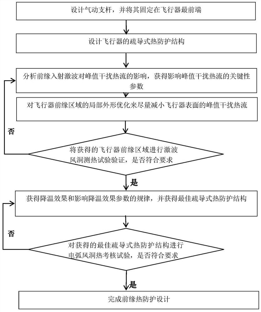
The invention relates to a thermal protection method for the leading edge of a hypersonic aircraft. Design the aerodynamic strut and fix it at the front end of the aircraft; design the air-draining thermal protection structure of the aircraft; obtain the key parameters that affect the peak disturbance heat flow; optimize the local shape of the aircraft's leading edge area; obtain the aircraft's leading edge area Conduct shock wave wind tunnel thermal test verification; complete the design of the dredging thermal protection structure, obtain the cooling effect and the law of the parameters affecting the cooling effect, and obtain the best dredging thermal protection structure; the best dredging thermal protection structure obtained Carry out the arc wind tunnel thermal assessment test; determine whether the design of the dredging thermal protection structure is completed according to the results of the thermal assessment test. The invention can ensure the feasibility of the thermal protection scheme of the leading edge area without reducing the overall performance index such as the lift-to-drag ratio of the aircraft, and can effectively solve the thermal protection problem of the leading edge area of ​​the hypersonic aircraft.

Description

technical field [0001] The invention belongs to the technical field of heat reduction and drag reduction of aircraft, and in particular relates to a thermal protection method for the leading edge of a hypersonic aircraft. Background technique [0002] For a hypersonic vehicle with a complex shape in the vicinity of a high Mach number, the shape of the high lift-to-drag ratio and the working requirements of the air-breathing engine make the radius of the leading edge of the projectile / protective cover not too large, and the leading edge area is subjected to severe aerodynamic heating. The enthalpy dissociated flow will also have complex nonlinear coupling with the thermal protection material, which puts forward extremely stringent requirements on the temperature resistance, oxidation resistance and reliability of the thermal protection structure in the leading edge area. At present, the commonly used thermal protection materials are difficult to ensure that the leading edge a...

Claims


Application Information

Patent Timeline
Patent Type & Authority Patents(China)
IPC IPC(8): B64C1/38B64C30/00
CPCB64C1/38B64C30/00Y02T90/00
Inventor 张红军李海群康宏琳査旭
Owner BEIJING AEROSPACE TECH INST
Learn More