Welding head for welding inner ring and main reinforcement of reinforcement cage
A welding machine head and steel cage technology, which is applied in welding equipment, welding equipment, auxiliary welding equipment, etc., can solve the problem of no automatic welding of main ribs and inner rings, reduce labor intensity, increase welding surface, and increase alignment of inner rings. The effect of the position of the circle
- Summary
- Abstract
- Description
- Claims
- Application Information
AI Technical Summary
Problems solved by technology
Method used
Image

Examples
Embodiment 1
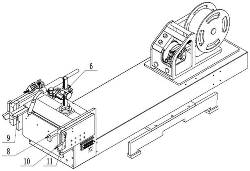
[0035] Such as figure 1 As shown, a welding head for welding the inner ring of the steel cage and the main reinforcement, including the head body, and the inner ring position detection mechanism 9, the inner ring position detection mechanism 9 is movably arranged in the left and right direction On the head body and can touch the inner ring, the inner ring position detection mechanism 9 determines the welding spot position between the inner ring and the main rib by touching the inner ring; it also includes a welding torch chuck 6. The welding torch chuck 6 cooperates with the inner ring position detection mechanism 9 and is movably arranged on the machine head body along the left and right directions. The welding torch chuck 6 is used to install the welding torch; it also includes the main rib fixing device A, which is arranged on On the machine head body, it is used to fix the main ribs. When this embodiment is working, the main ribs are preset at the positions to be welded o...
Embodiment 2
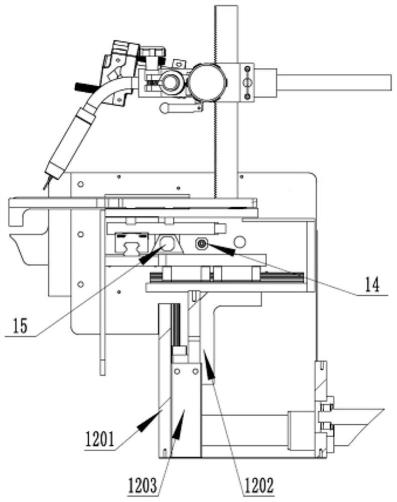
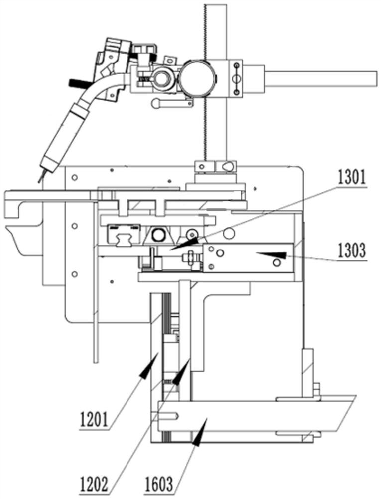
[0039] Such as Figure 1-3 Shown is a welding machine head for welding the inner ring of the reinforcement cage and the main reinforcement. On the basis of Embodiment 1, the first driving device is driven and connected with the upper and lower bases 1202, and drives the upper and lower bases 1202 to move in the up and down direction ; The second driving device includes a driving connection with the horizontal base 1301, driving the horizontal base 1301 to move in the front and back direction. The second driving device drives the horizontal base 1301 to move so as to drive the main rib fixing block 8 arranged on the horizontal base 1301 to move in the front-rear direction. In this embodiment, the upper and lower bases 1202 are designed with slide rails, the first driving device is located at the upper and lower cylinders 1203, and the upper and lower cylinders 1203 are installed on the machine head body through the vertical base 1201, and the upper and lower bases 1202 are conn...
Embodiment 3
[0046] Such as Figure 4 Shown is a welding machine head for welding the inner ring of the reinforcement cage and the main reinforcement. On the basis of Embodiment 1, this embodiment is also provided with a third driving device. The third driving device includes a sliding base 1601, a forward Motor 1602 and guide shaft 1603, the forward motor 1602 is connected to the guide shaft 1603 through the transmission block 1605, the guide shaft 1603 passes through the guide slider 1604 and is installed on the sliding base 1601, one end of the guide shaft 1603 is connected to the vertical The straight bases 1201 are connected, and the forward motor 1602 is used to drive the whole structure to move along the front and rear directions. The third driving device is used to drive the body part of the machine head where the welding gun chuck 6 is located, which includes the first driving device, the second driving device, the main rib fixing block 8, the main rib supporting block 10, the inn...
PUM
 Abstract
Description
Claims
Application Information
 - R&D
- Intellectual Property
- Life Sciences
- Materials
- Tech Scout
- Unparalleled Data Quality
- Higher Quality Content
- 60% Fewer Hallucinations
Browse by: Latest US Patents, China's latest patents, Technical Efficacy Thesaurus, Application Domain, Technology Topic, Popular Technical Reports.
© 2025 PatSnap. All rights reserved.Legal|Privacy policy|Modern Slavery Act Transparency Statement|Sitemap|About US| Contact US: help@patsnap.com