A filter device for chemical waste liquid with split flow and anti-clogging

A filter device and anti-clogging technology, which is applied in the chemical industry, can solve the problems of inability to guarantee the cleaning effect, blockage of the filter screen, unfavorable sedimentation of chemical waste liquid particles, etc., and achieve the effect of convenient backwashing operation and slowing down the flow rate of waste liquid

Active Publication Date: 2022-03-08
潍坊市环海化工有限公司
View PDF3 Cites 0 Cited by
  • Summary
  • Abstract
  • Description
  • Claims
  • Application Information

AI Technical Summary

Problems solved by technology

[0006] The purpose of the present invention is to provide a chemical waste liquid filter device with shunt flow and anti-clogging, to solve the existing chemical waste liquid filter device on the market proposed by the above background technology, when the chemical waste liquid enters the filter device through the pipeline When the waste liquid enters, it will cause the fluctuation of the waste liquid inside the filter equipment, which is not conducive to the precipitation of particles in the initial chemical waste liquid, and is not conducive to the initial filtration of the chemical waste liquid, that is, it cannot follow the flow of the waste liquid inside the filter equipment in time. The height of the surface controls the inflow, and it is easy to cause the particles in the chemical waste liquid to block the filter screen, which is inconvenient for subsequent cleaning of the filter screen. During reverse flushing, the cleaning effect cannot be guaranteed only by the impact of water flow

Method used


Image

  • A filter device for chemical waste liquid with split flow and anti-clogging
  • A filter device for chemical waste liquid with split flow and anti-clogging
  • A filter device for chemical waste liquid with split flow and anti-clogging

Examples


Embodiment Construction

[0029] Based on the embodiments of the present invention, all other embodiments obtained by persons of ordinary skill in the art without making creative efforts belong to the protection scope of the present invention.

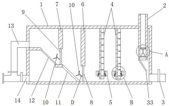
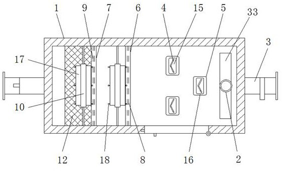
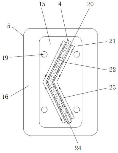
[0030] see Figure 1-10 , the present invention provides a technical solution: a chemical waste liquid filter device with shunt flow and anti-clogging, including filter device body 1, waste liquid pipe 2, waste water pipe 3, splitter plate 4, cleaning sleeve 5, first barrier plate 6 , the second barrier plate 7, the first filter screen 8, the second filter screen 9, the vibrating roller 10, the guide plate 11, the third filter screen 12, the cleaning pipe 13, the liquid outlet pipe 14, the sliding block 15, the floating ball 16 , rotating blade 17, hitting ball 18, support frame 19, chute 20, deflection groove 21, deflection plate 22, cleaning brush 23, diversion hole 24, sealing tray 25, support rod 26, sealing groove 27, sealing protrusion 28, Limiting frame...


PUM


Abstract

The invention discloses a filter device for chemical waste liquid with shunt flow and anti-clogging, which comprises a filter device body, a waste liquid pipe, a waste water pipe and a liquid outlet pipe. The top side of the filter device body is welded with a vertically placed waste liquid filter. liquid pipe, and the lower part of the filter device body close to the waste liquid pipe side is welded with a waste water pipe, and the filter device body on the side of the waste liquid pipe away from the waste water pipe is vertically provided with a splitter plate, and the first filter screen and A vibrating roller is arranged on the side of the second filter screen away from the diverter plate, and the bottom of the cleaning pipe is connected with the liquid outlet pipe at the bottom of the filter device body. The chemical waste liquid filtration device with shunt flow and anti-clogging can filter the chemical waste water, and can follow the liquid level height of the waste liquid inside the filter equipment to control the inflow of the chemical waste water in time to avoid the inflow of the waste water If it is too large, it will cause the waste water inside the filter equipment to move, which is convenient for the subsequent backwash operation of the filter equipment.

Description

technical field [0001] The invention relates to the technical field of chemical industry, in particular to a filter device for chemical waste liquid with split flow and anti-clogging. Background technique [0002] The chemical waste liquid filtration device is mainly a device for filtering the waste chemical waste liquid generated by chemical enterprises during the production process. It can filter the particles or harmful substances in the chemical waste liquid, so that the discharged chemical waste The liquid meets the discharge requirements and avoids polluting the environment. [0003] The existing chemical waste liquid filtration device has the following problems when filtering waste chemical waste liquid: [0004] 1. When the chemical waste liquid enters the filter equipment through the pipeline, the waste liquid will cause the fluctuation of the waste liquid inside the filter equipment, which is not conducive to the precipitation of particles in the initial chemical ...

Claims


Application Information

Patent Timeline
Patent Type & Authority Patents(China)
IPC IPC(8): B01D36/04B01D35/16
CPCB01D36/04B01D35/16
Inventor 张少康
Owner 潍坊市环海化工有限公司
Why Eureka
Try Eureka