Signal detection system and method for multi-channel filter

A signal detection and detection system technology, applied in transmission systems, waveguide devices, electrical components, etc., can solve problems such as inability to collect data uniformly, large fluctuations in spectrum analyzer values, and difficulty for new employees to get started.

Pending Publication Date: 2021-01-05
安徽沃信通信科技有限公司
View PDF3 Cites 0 Cited by
  • Summary
  • Abstract
  • Description
  • Claims
  • Application Information

AI Technical Summary

Problems solved by technology

[0003] In the past, the filter was tested for signal leakage. There was no systematic construction method. It used to connect a single signal source while maintaining the continuous output of the signal. One end of a single cable was connected to a channel connector of the filter. The accessories are moved randomly, the other end of the probe is connected to the spectrum analyzer, the value of the spectrum analyzer is manually checked, judged and manually recorded, and the same action needs to be repeated for e...

Method used


Image

  • Signal detection system and method for multi-channel filter
  • Signal detection system and method for multi-channel filter

Examples


Embodiment Construction

[0023] Referring to the accompanying drawings, through the description of the embodiments, the specific implementation of the present invention, such as the shape, structure, mutual position and connection relationship between the various parts, the function and working principle of each part, and the manufacturing process And the method of operation and use, etc., are described in further detail to help those skilled in the art have a more complete, accurate and in-depth understanding of the inventive concept and technical solutions of the present invention.

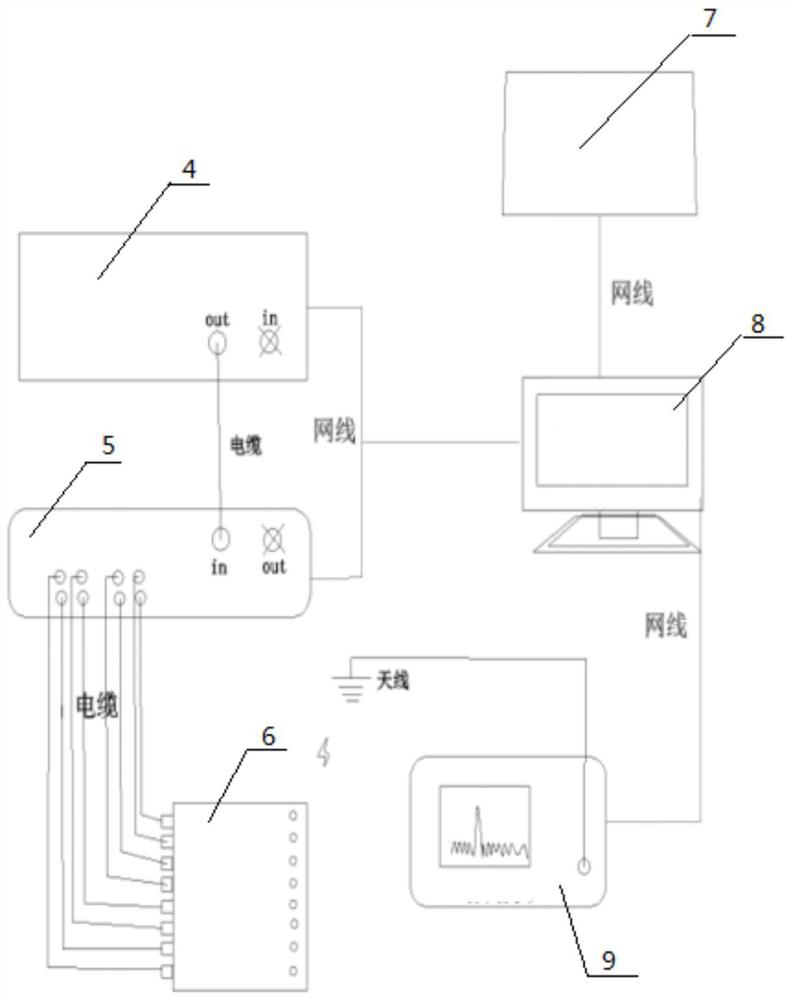
[0024] figure 2 It is the hardware connection diagram of the signal detection system in the present invention, as figure 2 A signal detection system for a multi-channel filter is shown, the signal input terminal of the detection system is connected to the signal output terminal of the filter to be filtered, and the detection system includes a server terminal 7, a PC operation terminal 8, and a control switch module 5...


PUM


Abstract

The invention discloses a signal detection system for a multi-channel filter, and the signal input end of the detection system is connected with the signal output end of a to-be-filtered filter; the detection system comprises a server terminal, a PC operation end, a control switch module, a detection component and a frequency spectrograph, wherein the PC operation end and the control switch moduleare both connected to a network signal source, the signal output end of the control switch module is connected with the detection component, the PC operation end controls the detection component to be opened and closed through the control switch module, the PC operation end is in communication connection with the server terminal through a network, and the other signal output end of the PC operation end is connected to the frequency spectrograph; the invention further discloses a signal detection method for the multi-channel filter. The signal detection system is used for detecting all components in the filter; by adopting the system and the method disclosed in the technical scheme, the test efficiency is improved, the missed test and wrong test conditions are prevented, and the method issuitable for signal detection of various filters.

Description

technical field [0001] The invention belongs to the field of filters, and more specifically, the invention relates to a signal detection system and method for multi-channel filters. Background technique [0002] Cavity filters are widely used in aviation, aerospace, radar, communications, electronic countermeasures, radio and television and various electronic test equipment. With the rapid development of modern mobile communication technology, especially the rapid development of the new generation of communication base station systems, the cavity Demand for filters has skyrocketed, putting pressure on filter deliveries and product quality. Due to the increasing requirements for the size and types of filters, most cavity filters now adopt a multi-channel centralized structural design method, which requires high structural sealing to avoid signal leakage and poor electrical performance of the whole machine. Therefore, more and more attention is paid to the signal leakage of p...

Claims


Application Information

Patent Timeline
IPC IPC(8): H04L29/08H01P1/208
CPCH04L67/125H01P1/208
Inventor 丁峰峰
Owner 安徽沃信通信科技有限公司
Why Eureka
Try Eureka