
Distributed solar energy storage system

An energy storage system and solar energy technology, applied in the field of solar energy storage, can solve the problems of increasing the difficulty and risk of photovoltaic module installation, energy, collection equipment, waste of space resources, and the inability of photovoltaic modules to collect light energy, so as to avoid Unable to provide normal power supply, ensure sustainable operation, and easy installation

Pending Publication Date: 2021-01-05
东山神盾新能源科技有限公司
View PDF3 Cites 0 Cited by
  • Summary
  • Abstract
  • Description
  • Claims
  • Application Information

AI Technical Summary

Problems solved by technology

This cluster installation mode has relatively strict requirements on the installation space. In non-open environments such as remote mountainous areas, outlying islands, and the wild, it is impossible to maximize energy collection, that is, when the sun is moving, shadows will cover photovoltaic modules. It makes it impossible for photovoltaic modules to collect light energy, resulting in low efficiency of light energy collection. At the same time, it increases the difficulty and risk of installation of photovoltaic modules, and also causes a great waste of energy, collection equipment, and space resources.
And because the source of photovoltaic energy is the sun, and the position of the sun is dynamic every day, while the position of the photovoltaic module is static relative to the sun, which also leads to the fact that if the photovoltaic module is to ensure that it is always at the angle of direct sunlight, it must follow the The orientation of the panel and the position of the mobile photovoltaic module are changed according to the moving track of the sun, and the objective conditions required to realize the design of this system are relatively strict, and the technical and economic costs are relatively high

Method used


Image

  • Distributed solar energy storage system
  • Distributed solar energy storage system
  • Distributed solar energy storage system

Examples


Embodiment Construction

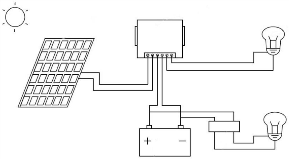
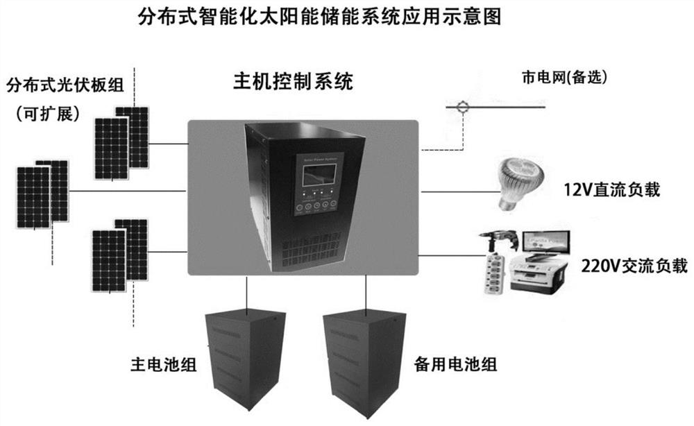
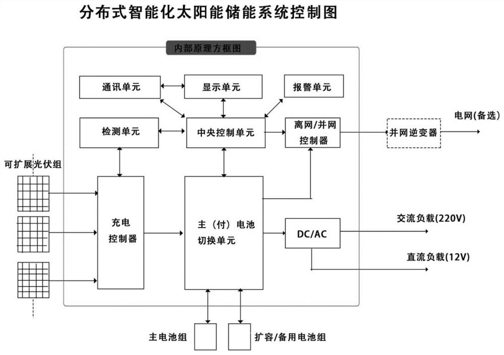
[0036] In order to facilitate the understanding of those skilled in the art, the structure of the present invention will be further described in detail with reference to the accompanying drawings:

[0037] refer to Figure 1-4 , a distributed solar energy storage system, comprising:

[0038] Several photovoltaic modules for receiving and collecting solar energy, the photovoltaic modules include several solar cell panels, the several solar cell panels are distributed along the movement track of the sunlight, and the angle between the solar cell panels and the horizontal plane can be adjusted ;

[0039] An intelligent monitoring module, connected to each photovoltaic module, is used to obtain the illumination time and illumination amount of each photovoltaic module, and intelligently calculate the optimal distribution angle of several photovoltaic modules according to the illumination time and illumination amount, and adjust the solar energy The angle between the panel and the...


PUM


Abstract

The invention relates to a distributed solar energy storage system which comprises a plurality of photovoltaic modules used for receiving and collecting solar energy, wherien each photovoltaic modulecomprises a plurality of solar cell panels, the plurality of solar cell panels are distributed along the movement track of sunlight, and the included angle between each solar cell panel and the horizontal plane is adjustable; an intelligent monitoring module which is connected to each photovoltaic module and is used for obtaining the illumination time and the illumination quantity of each photovoltaic module, intelligently calculating the optimal distribution angle of the plurality of photovoltaic modules according to the illumination time and the illumination quantity, and adjusting the included angle between the solar cell panel and the horizontal plane; an AI detection module which is used for acquiring image information of the main energy storage module, analyzing the image informationthrough AI data processing and judging whether the main energy storage module works normally or not; a control system which is electrically connected with the photovoltaic module and the energy storage module, and controls the on-off of the power change-over switch and the relay switch.

Description

technical field [0001] The invention relates to the field of solar energy storage, in particular to a distributed solar energy storage system. Background technique [0002] With the rapid development of new energy technology, photovoltaic solar power generation has become a trend. However, solar energy can generate electricity during the day when the sun is there, but cannot generate electricity or generate less electricity at night or when there is no sun on cloudy and rainy days. It is very unstable, so it is necessary to store the electric energy generated by solar energy in the battery module, and then the battery module can output electric energy stably. [0003] The collection of solar energy is completed by photovoltaic modules. When conventional photovoltaic modules collect light energy, they are mostly installed in a clustered square array. This cluster-type installation mode has strict requirements on the installation space. In remote mountainous areas, outlying i...

Claims


Application Information

Patent Timeline
Patent Type & Authority Applications(China)
IPC IPC(8): H02J7/35H02S40/38
CPCH02J7/35H02S40/38Y02E10/56Y02E70/30
Inventor 林志刚
Owner 东山神盾新能源科技有限公司
Learn More