
Wind driven generator yawing device

A wind turbine and yaw technology, which is applied in the direction of wind turbines, wind turbine control, wind power generation, etc., can solve the problems of long untwisting time, yaw axis braking, and low stability of the yaw axis position, etc. , to achieve the effect of improving reliability and stability

Active Publication Date: 2021-01-05
云南滇能智慧能源有限公司
View PDF9 Cites 0 Cited by
  • Summary
  • Abstract
  • Description
  • Claims
  • Application Information

AI Technical Summary

Problems solved by technology

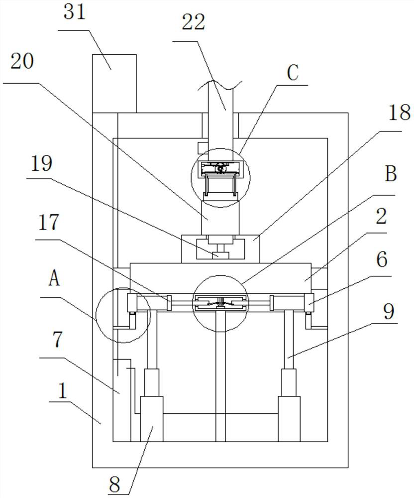
[0004] In view of this, in order to solve the problem that the traditional yaw device of the wind power generator cannot brake the yaw axis after yaw, the position stability of the yaw axis is not high, and the cable is directly wound around the yaw axis In the above, when too many cables are wound on the yaw axis, it is necessary to untie the cable and then carry out the yaw operation, which takes a long time to untie the cable, which affects the working efficiency of the wind turbine, and provides a wind turbine yaw device

Method used


Image

  • Wind driven generator yawing device
  • Wind driven generator yawing device
  • Wind driven generator yawing device

Examples


Embodiment Construction

[0028] Embodiments of the present invention are described below through specific examples, and those skilled in the art can easily understand other advantages and effects of the present invention from the content disclosed in this specification. The present invention can also be implemented or applied through other different specific implementation modes, and various modifications or changes can be made to the details in this specification based on different viewpoints and applications without departing from the spirit of the present invention. It should be noted that the diagrams provided in the following embodiments are only schematically illustrating the basic concept of the present invention, and the following embodiments and the features in the embodiments can be combined with each other in the case of no conflict.

[0029] Wherein, the accompanying drawings are for illustrative purposes only, and represent only schematic diagrams, rather than physical drawings, and should...


PUM


Abstract

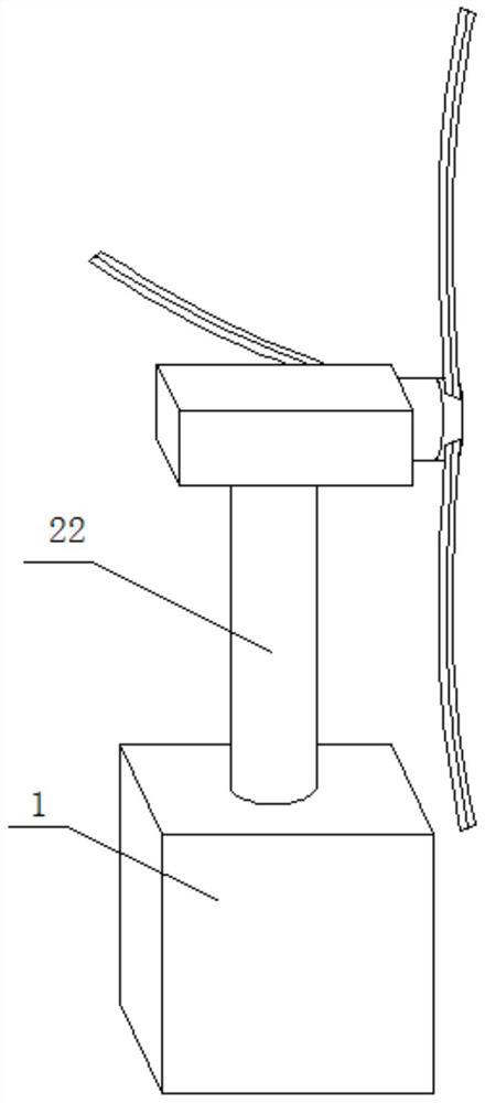
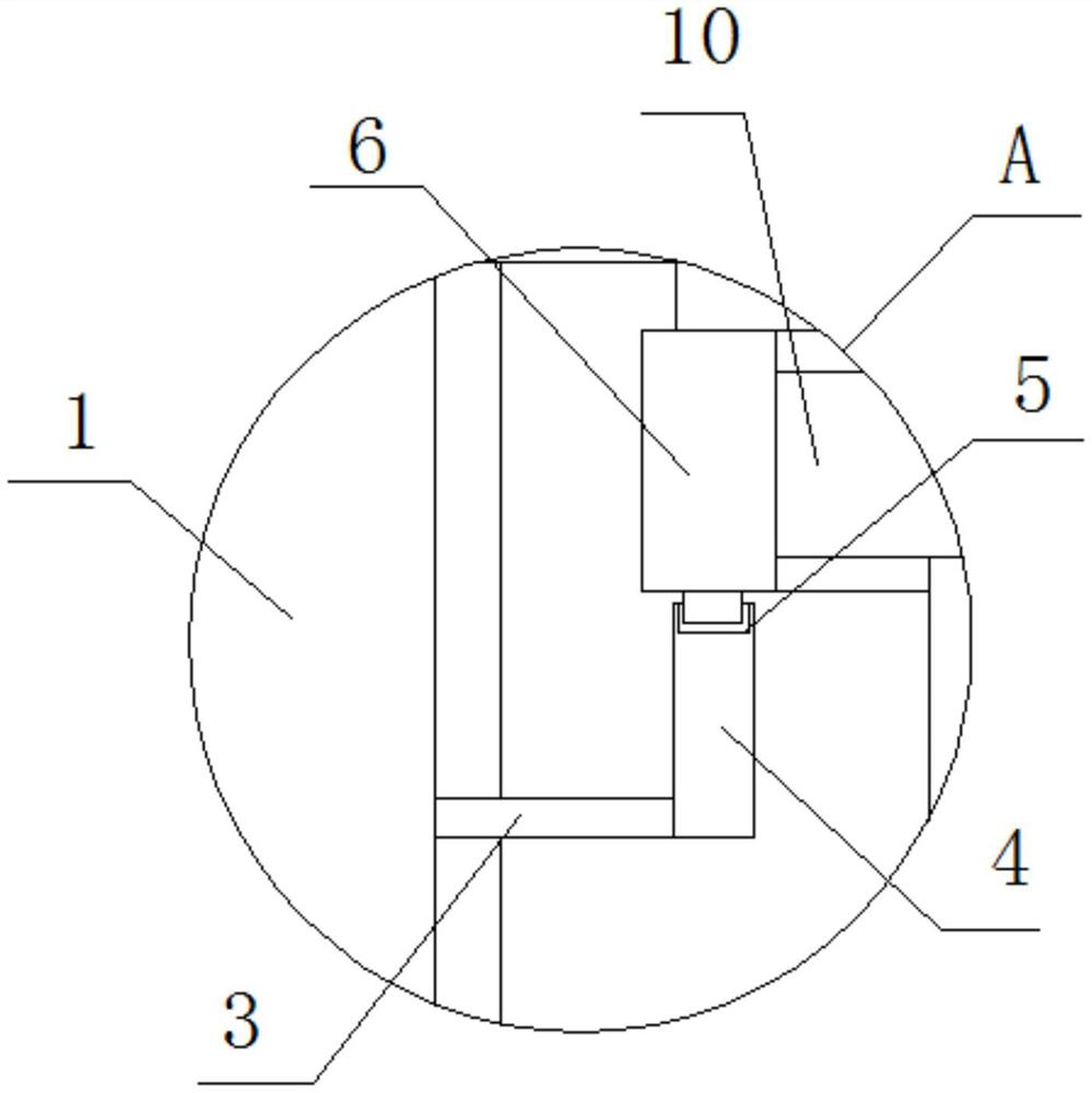
The invention belongs to the field of wind driven generators, and particularly relates to a wind driven generator yawing device. According to the yawing device, an annular inner rack is fixedly installed at the bottom of a bracket in an equipment box; a limiting assembly is arranged at the bottom of the annular inner rack; the annular inner rack is in transmission connection with a yawing assembly; a cable unwinding chamber is fixedly installed at the top of the bracket; a cable unwinding motor is fixedly installed on the inner wall of the bottom of the cable unwinding chamber; the top of a rotating shaft of the cable unwinding motor penetrates through the inner wall of the top of the cable unwinding chamber and extends to the position above the cable unwinding chamber; a cable unwinding shaft is fixedly installed at the top of the rotating shaft; a clamping plate is fixedly installed at the top of the cable unwinding shaft; a yawing shaft is rotationally installed at the top of the cable unwinding shaft; the top of the yaw shaft penetrates through the interior of the top of the equipment box and extends to the position above the equipment box; a clamping block is fixedly installedon one side of the yawing shaft; and a driving shaft is rotationally installed on the inner wall of one side of the clamping block. The yawing device consumes less time in cable unwinding and is highin efficiency, the yawed yaw shaft can be braked, and the stability and reliability are high.

Description

technical field [0001] The invention belongs to the field of wind power generators, and relates to a wind power generator yaw device. Background technique [0002] A wind turbine is a power device that converts wind energy into mechanical work, which drives the rotor to rotate, and finally outputs alternating current. A wind turbine generally includes a wind wheel, a generator (including devices), a steering device (tail), a tower, and a limiter. The working principle of the wind turbine is relatively simple. The wind rotor rotates under the action of the wind. It converts the kinetic energy of the wind into the mechanical energy of the wind rotor shaft, and the generator rotates under the drive of the wind rotor shaft. generate electricity. [0003] The yaw device of the existing wind turbine cannot brake the yaw axis after yaw, resulting in the position stability of the yaw axis is not high, the cable is directly wound on the yaw axis, when the yaw axis When there are to...

Claims


Application Information

Patent Timeline
Patent Type & Authority Applications(China)
IPC IPC(8): F03D7/02F03D7/04
CPCF03D7/0204F03D7/042Y02E10/72
Inventor 张浪
Owner 云南滇能智慧能源有限公司
Learn More