Turbine blade trailing edge slit cooling structure adopting wavy partition ribs
A technology for turbine blades and cooling structures, which is applied to the supporting elements of blades, engine elements, machines/engines, etc., can solve the problems of reducing the temperature level of the trailing edge area of the blade, and it is difficult to meet the cooling requirements of the trailing edge of the turbine blade. Cooling effect, increased convective heat transfer area, and enhanced heat transfer capacity
- Summary
- Abstract
- Description
- Claims
- Application Information
AI Technical Summary
Problems solved by technology
Method used
Image

Examples
Embodiment 1
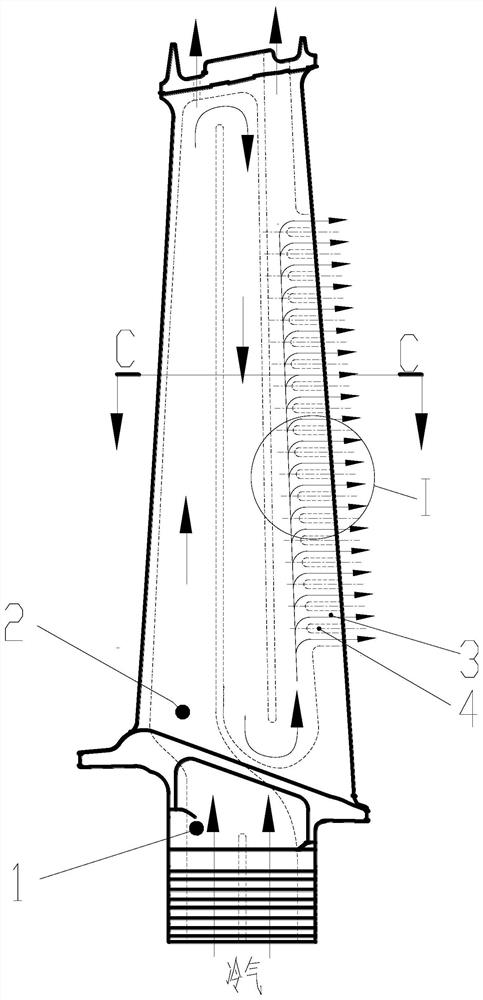
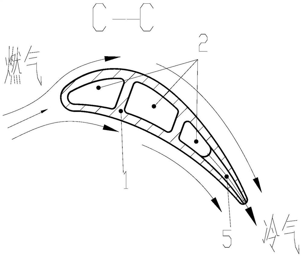
[0035] Please refer to Figure 2. A turbine blade trailing edge slit structure adopting wave-type ribs, comprising a hollow turbine blade 1, an inner cavity cold air channel 2, a trailing edge exhaust slit channel 3 and a trailing edge slit rib 4;
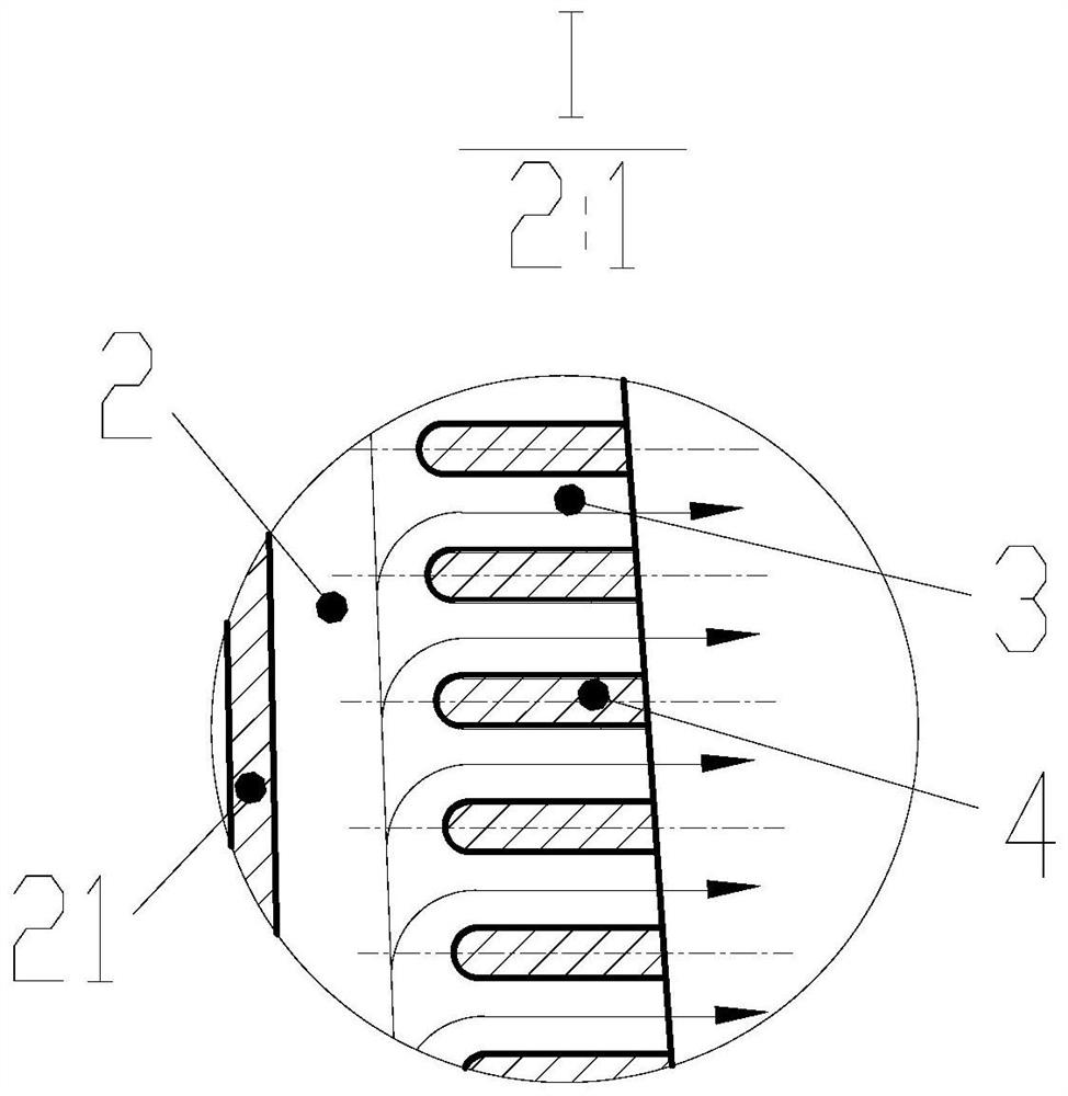
[0036] The hollow turbine blade 1 is provided with a cold air channel 2 in the inner cavity, and a wave-shaped trailing edge exhaust slot 5 is opened along the chord direction at the trailing edge, and a plurality of wave-shaped trailing edge slots are evenly arranged inside it. The partition ribs 4 are arranged side by side to form discrete trailing edge exhaust slit channels 3 . Along the chord direction, the channel is in the shape of a wave with gradually attenuating amplitude and width, and its shape can be controlled by the central line 6 viewed from the slit. Typically, the centerline is designed with two peaks and troughs in the top view dimension, and its amplitude A x 0.3 times the thickness of the local leaf shape, ampl...
Embodiment 2
[0038] Please refer to Figure 2. A turbine blade trailing edge slit structure adopting wave-type ribs, comprising a hollow turbine blade 1, an inner cavity cold air channel 2, a trailing edge exhaust slit channel 3 and a trailing edge slit rib 4;
[0039] The hollow turbine blade 1 is provided with a cold air channel 2 in the inner cavity, and a wave-shaped trailing edge exhaust slot 5 is opened along the chord direction at the trailing edge, and a plurality of wave-shaped trailing edge slots are evenly arranged inside it. The partition ribs 4 are arranged side by side to form discrete trailing edge exhaust slit channels 3 . Along the chord direction, the channel is in the shape of a wave with gradually attenuating amplitude and width, and its shape can be controlled by the central line 6 viewed from the slit. Typically, the centerline is designed with two peaks and troughs in the top view dimension, and its amplitude A x 0.3 times the thickness of the local leaf shape, ampl...
Embodiment 3
[0041] Please refer to Figure 2. A turbine blade trailing edge slit structure adopting wave-type ribs, comprising a hollow turbine blade 1, an inner cavity cold air channel 2, a trailing edge exhaust slit channel 3 and a trailing edge slit rib 4;
[0042] The hollow turbine blade 1 is provided with a cold air channel 2 in the inner cavity, and a wave-shaped trailing edge exhaust slot 5 is opened along the chord direction at the trailing edge, and a plurality of wave-shaped trailing edge slots are evenly arranged inside it. The partition ribs 4 are arranged side by side to form discrete trailing edge exhaust slit channels 3 . Along the chord direction, the channel is in the shape of a wave with gradually attenuating amplitude and width, and its shape can be controlled by the central line 6 viewed from the slit. Typically, the centerline is designed with 8 peaks and troughs in the top view dimension, and its amplitude A x 0.1 times the thickness of the local airfoil, amplitude...
PUM
 Abstract
Description
Claims
Application Information
 - R&D
- Intellectual Property
- Life Sciences
- Materials
- Tech Scout
- Unparalleled Data Quality
- Higher Quality Content
- 60% Fewer Hallucinations
Browse by: Latest US Patents, China's latest patents, Technical Efficacy Thesaurus, Application Domain, Technology Topic, Popular Technical Reports.
© 2025 PatSnap. All rights reserved.Legal|Privacy policy|Modern Slavery Act Transparency Statement|Sitemap|About US| Contact US: help@patsnap.com