
Photo-thermal collection type energy-saving building curtain wall

A collection-type, architectural technology, applied in buildings, building components, sustainable buildings, etc., can solve the problems of poor luminous flux, increased use costs, increased purchase costs, etc., to improve power generation efficiency, reduce use costs, and improve The effect of light brightness

Active Publication Date: 2021-01-05
怀化简美装饰设计工程有限公司
View PDF7 Cites 2 Cited by
  • Summary
  • Abstract
  • Description
  • Claims
  • Application Information

AI Technical Summary

Problems solved by technology

[0002] Building curtain wall is a commonly used exterior wall decoration at present. It is not used as a load-bearing exterior wall. Due to the large surface area of ​​the building curtain wall after laying, many people tend to design the building curtain wall as a photovoltaic curtain wall. However, due to the installation of photovoltaic curtain walls, resulting in The indoor illuminance of the building is insufficient, so that the external light cannot enter the room through the curtain wall, resulting in insufficient indoor light during the day and a dim situation. At present, some photovoltaic curtain wall panels that can be pulled by hand can be opened to meet the light injection. However, because the opening method is based on motors, etc., the use cost increases, the purchase cost increases, and it is easy to be damaged, and the opened photovoltaic curtain wall panels are not fully opened due to the included angle of travel, so the luminous flux is actually not very good

Method used


Image

  • Photo-thermal collection type energy-saving building curtain wall
  • Photo-thermal collection type energy-saving building curtain wall
  • Photo-thermal collection type energy-saving building curtain wall

Examples


Embodiment Construction

[0019] All features disclosed in this specification, or steps in all methods or processes disclosed, may be combined in any manner, except for mutually exclusive features and / or steps.

[0020] Any feature disclosed in this specification (including any appended claims, abstract and drawings), unless expressly stated otherwise, may be replaced by alternative features which are equivalent or serve a similar purpose. That is, unless expressly stated otherwise, each feature is one example only of a series of equivalent or similar features.

[0021] In describing the present invention, it is to be understood that the terms "one end", "the other end", "outer side", "upper", "inner side", "horizontal", "coaxial", "central", "end ", "length", "outer end" and other indicated orientations or positional relationships are based on the orientations or positional relationships shown in the drawings, which are only for the convenience of describing the present invention and simplifying the d...


PUM


Abstract

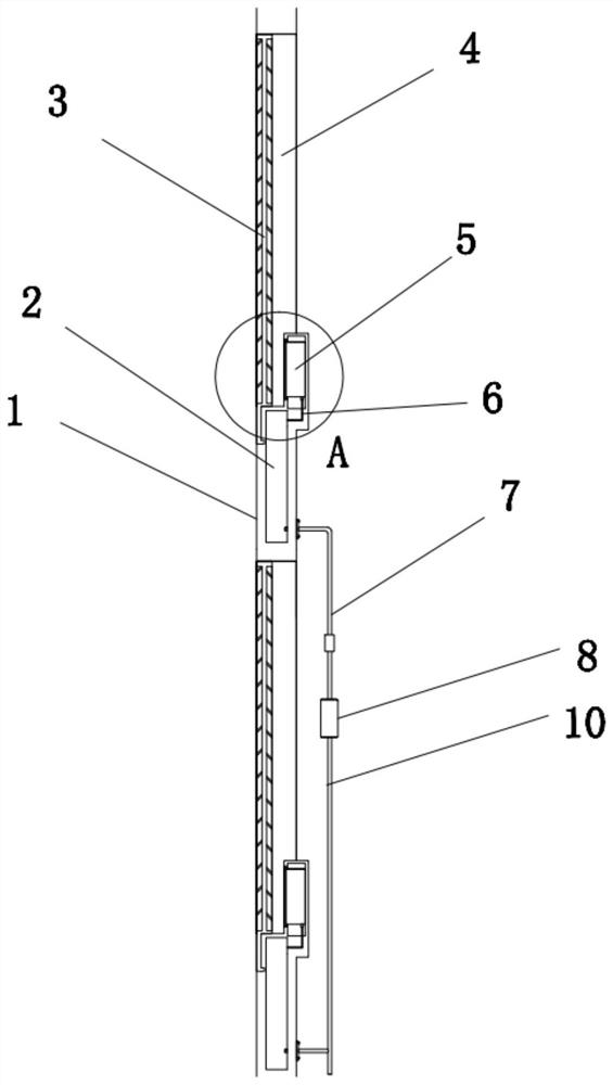
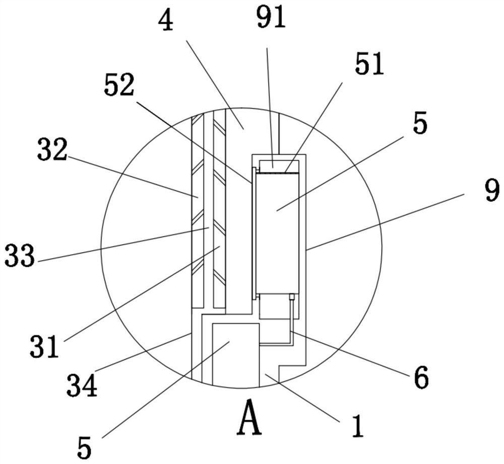
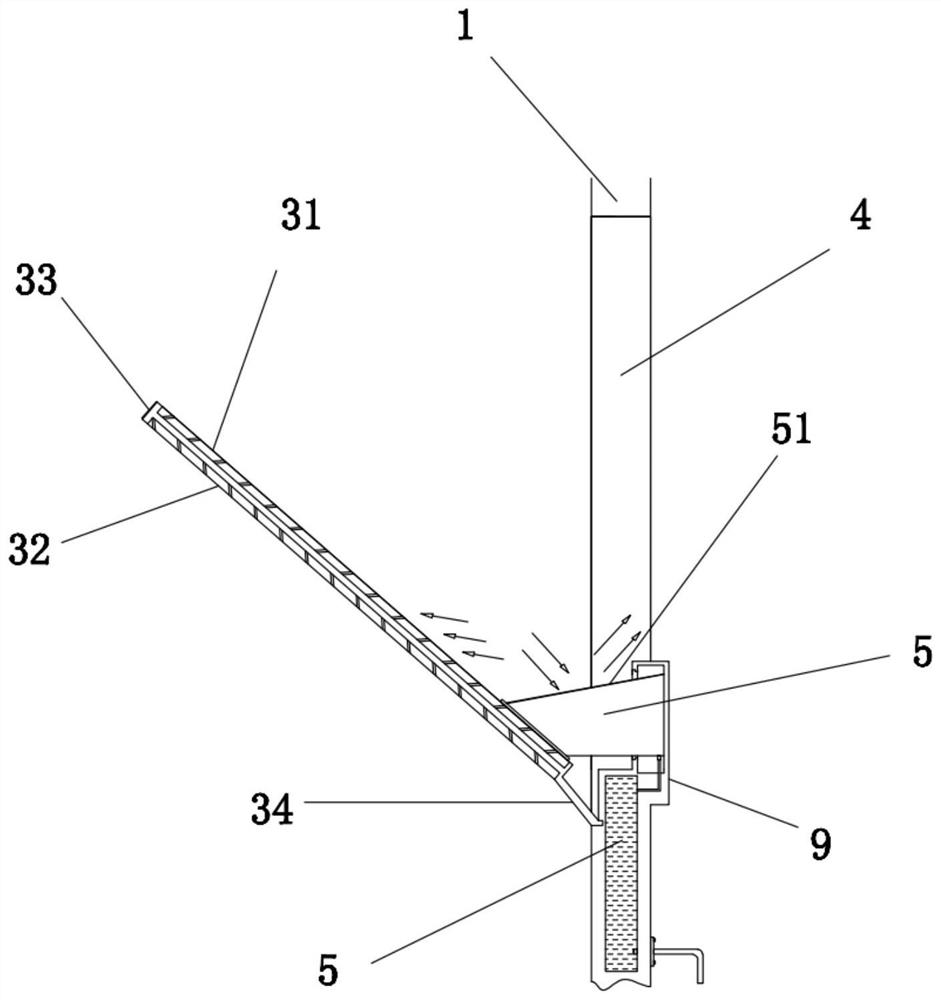
The invention discloses a photo-thermal collection type energy-saving building curtain wall. The photo-thermal collection type energy-saving building curtain wall comprises a hollow keel support fixedly installed outside the outer wall face of a building, wherein one or more installation cavities are formed in the hollow keel support at equal intervals; the outer side ends of the bottom faces of the installation cavities are each provided with a groove; an elastic connecting piece is installed in each groove; the other end of each elastic connecting piece is connected with a sealing framework;the outer side face of each sealing framework is a glass curtain wall plate; and the inner side face of each sealing framework is a photovoltaic power generation plate. The installation cavities aresealed through the whole sealing frameworks. According to the building curtain wall structure, the installation cavities are sealed at night and used for outer wall heat preservation, the sealing frameworks can be opened in the daytime to expose the photovoltaic power generation plates so that a light inlet cavity can be exposed, external light can penetrate through the light inlet cavity to entera room, and the luminous flux is increased; and meanwhile, the power generation rate is increased and the light incidence amount is increased through a reflective film layer, and the indoor brightness is higher in the daytime.

Description

technical field [0001] The invention relates to a building curtain wall, in particular to a light and heat collection type energy-saving building curtain wall. Background technique [0002] Building curtain wall is a commonly used exterior wall decoration at present. It is not used as a load-bearing exterior wall. Due to the large surface area of ​​the building curtain wall after laying, many people tend to design the building curtain wall as a photovoltaic curtain wall. However, due to the installation of photovoltaic curtain walls, resulting in The illuminance in the interior of the building is insufficient, so that the external light cannot enter the room through the curtain wall, resulting in insufficient indoor light during the day and a dim situation. At present, some photovoltaic curtain wall panels that can be pulled by hand can be opened to meet the light injection. However, because the opening method is based on motors, etc., the use cost increases, the purchase co...

Claims


Application Information

Patent Timeline
Patent Type & Authority Applications(China)
IPC IPC(8): E04B2/88E04B2/96H02S20/22H02S40/22H02S30/00H02S40/00F24S30/425
CPCE04B2/88E04B2/885H02S20/22H02S40/22H02S30/00H02S40/00F24S30/425Y02B10/10Y02B10/20Y02E10/47Y02E10/52
Inventor 刘赛明
Owner 怀化简美装饰设计工程有限公司
Learn More