Compact fluorescent lamp
A fluorescent lamp, compact technology, applied in the use of discharge lamps, gas discharge lamps, parts of gas discharge lamps, etc., can solve the problems of efficiency reduction, temperature rise, etc., to improve efficiency, reduce temperature rise, and length will shorten the effect
- Summary
- Abstract
- Description
- Claims
- Application Information
AI Technical Summary
Problems solved by technology
Method used
Image

Examples
Embodiment approach 1
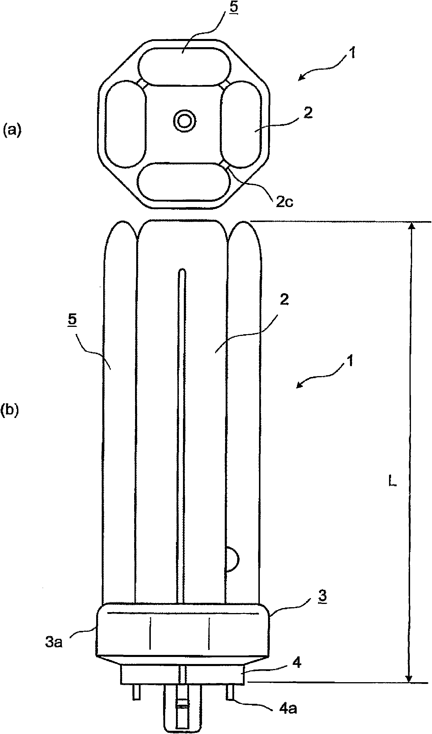
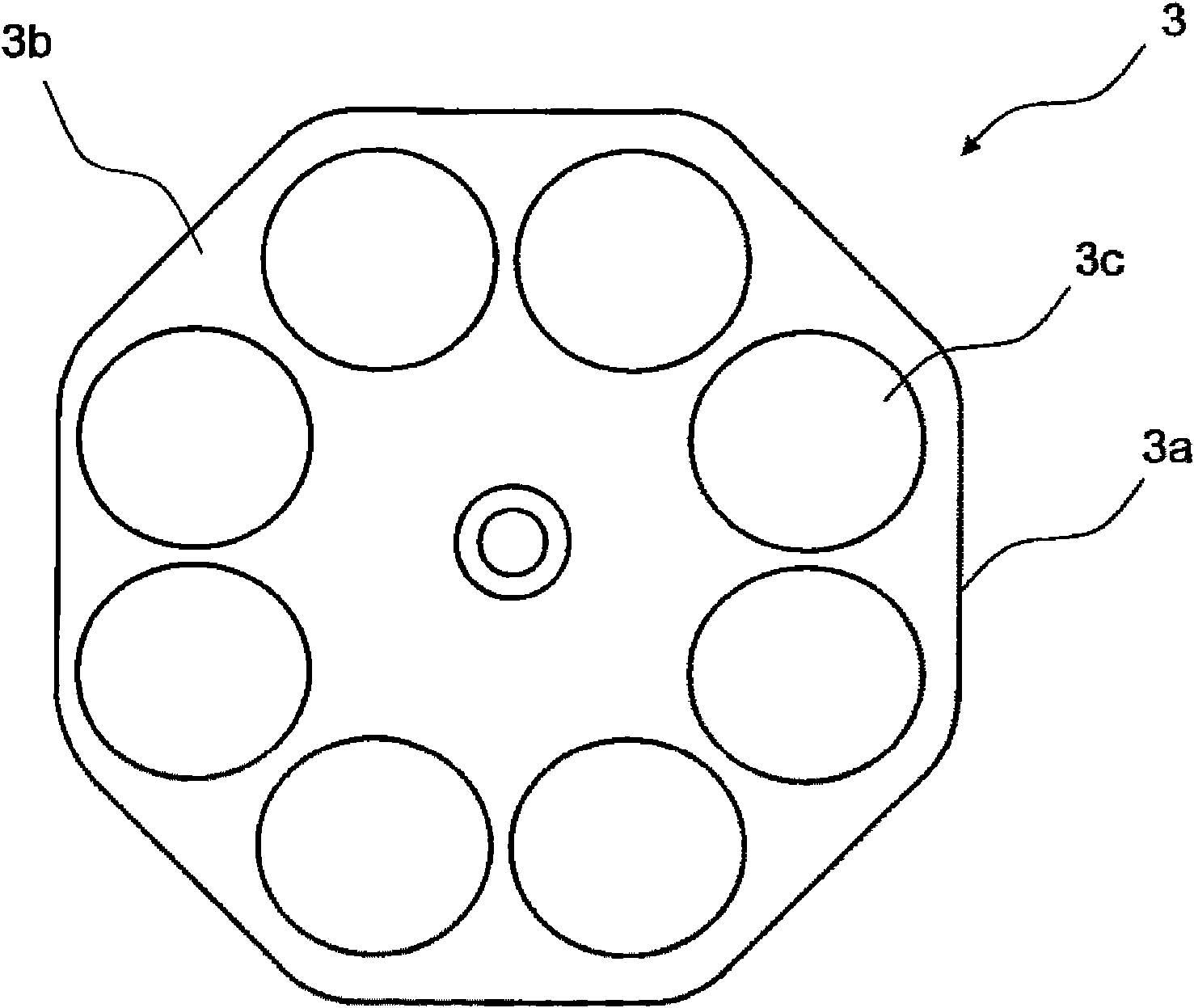
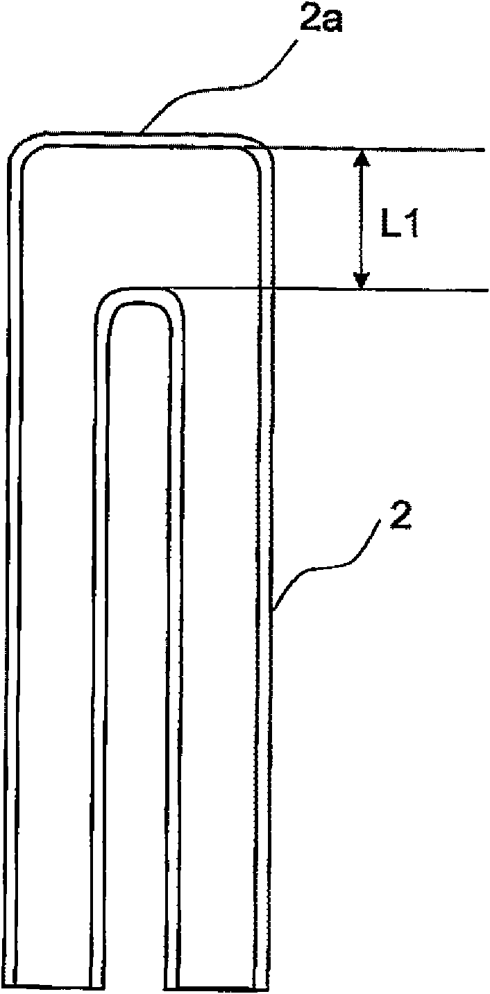
[0042] Figure 1 to Figure 6 is a diagram showing Embodiment 1, figure 1 It is a figure showing the overall structure of the compact fluorescent lamp 1 ((a) is a plan view, (b) is a front view), figure 2 is the top view of the lamp housing, image 3 is a partial longitudinal sectional view of the U-shaped tube 2, Figure 4 is a cross-sectional view of the U-shaped tube top 2a of the U-shaped tube 2, Figure 5 It is a figure which shows the 1st modification which combined the U-shaped tube 20 and the U-shaped tube 21 which differ in shape, Figure 6 It is a figure which shows the 2nd modification which combined the U-shaped tube 20 and the U-shaped tube 22 which differ in shape.
[0043] Such as figure 1 As shown, the compact fluorescent lamp 1 has: four U-shaped tubes 2 (glass lamp tubes) are fusion-bonded to each other between the side walls of the ends (joint portion 2a), thereby forming an internal whole formed by eight glass lamp tubes. On the top is a luminous tube 5...
Embodiment approach 2
[0081] Figure 7 It is a figure which shows Embodiment 2, and is a figure which shows the base line vicinity of the compact fluorescent lamp 1. FIG.
[0082] Since the luminous tubes 5 have 8 columns, the temperature of the luminous tubes 5 rises compared with a lamp with 6 columns of the same wattage. Therefore, the temperature of the base 4 also rises. The material of the lamp cap 3 is PET etc., so if the temperature of the lamp cap 4 rises, it will deteriorate. Therefore, in this embodiment, a method of lowering the temperature of the base 4 is considered.
[0083] The part relevant to the temperature of the lamp cap 4 is the filament 6 ( Figure 7 ), and the junction 2c between the U-shaped tubes 2 ( Figure 7). Both the filament 6 serving as a discharge starting point and the joint portion 2 c between the U-shaped tube 2 serving as a discharge circuit become high in temperature. Keeping the joint portion 2c between the filament 6 and the U-shaped tube 2 away from th...
Embodiment approach 3
[0091] Figure 8 ~ Figure 10 is a diagram showing Embodiment 3, Figure 8 is a diagram showing the overall structure of the compact fluorescent lamp 101, Figure 9 is a top view of the lamp base housing 103, Figure 10 is a partial longitudinal sectional view of the U-shaped tube 102 .
[0092] Such as Figure 8 As shown, the compact fluorescent lamp 101 has: four U-shaped tubes 102 (glass tubes) are fused and bonded to each other between the side walls of the ends (joint portion 102a), thereby forming an internal whole formed by eight glass tubes. The upper part is a luminous tube 105 with a serpentine discharge circuit, which has a flat part 103b for fixing the luminous tube 105 by bonding or the like, and a lamp base housing 103 with an octagonal side wall 103a in cross section connected to the flat part 103b , a base 104 having a base pin 104 a fitted in the base case 103 and electrically connected to the lead wire of the arc tube 105 .
[0093] Although not shown in ...
PUM
| Property | Measurement | Unit |
|---|---|---|
| Length | aaaaa | aaaaa |
| Length | aaaaa | aaaaa |
Abstract
Description
Claims
Application Information
 - Generate Ideas
- Intellectual Property
- Life Sciences
- Materials
- Tech Scout
- Unparalleled Data Quality
- Higher Quality Content
- 60% Fewer Hallucinations
Browse by: Latest US Patents, China's latest patents, Technical Efficacy Thesaurus, Application Domain, Technology Topic, Popular Technical Reports.
© 2025 PatSnap. All rights reserved.Legal|Privacy policy|Modern Slavery Act Transparency Statement|Sitemap|About US| Contact US: help@patsnap.com