Method for designing planar through-hole array filter layer, filter layer and LCD backlight screen

A filter layer and array technology, which is applied in the field of optical display, can solve the problems of inability to design aperture parameters in wavelength ratio and difficult implementation of pixel light transmittance, and achieve the effect of suppressing high-order diffraction orders and ensuring luminous flux

Active Publication Date: 2021-04-20
UNIV OF ELECTRONICS SCI & TECH OF CHINA
View PDF5 Cites 0 Cited by
  • Summary
  • Abstract
  • Description
  • Claims
  • Application Information

AI Technical Summary

Problems solved by technology

However, in order to ensure the same luminous flux of different colors, the area of ​​the light aperture will be affected by the power spectrum of the backlight source, and the aperture parameters cannot be designed according to the wavelength ratio; technically difficult to implement

Method used


Image

  • Method for designing planar through-hole array filter layer, filter layer and LCD backlight screen
  • Method for designing planar through-hole array filter layer, filter layer and LCD backlight screen
  • Method for designing planar through-hole array filter layer, filter layer and LCD backlight screen

Examples


Embodiment Construction

[0025] The specific embodiments of the present invention are described below so that those skilled in the art can understand the present invention, but it should be clear that the present invention is not limited to the scope of the specific embodiments. For those of ordinary skill in the art, as long as various changes Within the spirit and scope of the present invention defined and determined by the appended claims, these changes are obvious, and all inventions and creations using the concept of the present invention are included in the protection list.

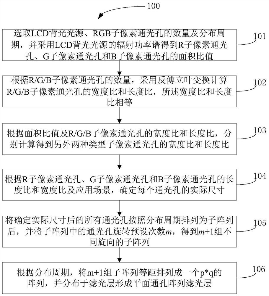
[0026] refer to figure 1 , figure 1 Shown is the method of utilizing the sinc function system to design the filter layer of the plane through-hole array; as figure 1 As shown, the method 100 includes steps 101 to 106.

[0027] In step 101, the number and distribution period of the LCD backlight light source and the RGB sub-pixel light holes are selected, and the radiation power spectrum of the LCD backlight light sourc...


PUM


Abstract

The invention discloses a method for designing a plane through-hole array filter layer by using a sinc function system, the filter layer and an LCD backlight screen. The method includes obtaining the area ratios of three types of through-holes by using the radiation power spectrum of the LCD backlight light source; According to the number of R / G / B sub-pixel light-through holes, use inverse Fourier transform to calculate the width ratio and length ratio of R / G / B sub-pixel light-through holes; calculate the width ratio and sum of the other two types of sub-pixel light-through holes Length ratio; according to the length ratio and width ratio of the three types of light holes and the application scene, determine the actual size of each light hole; after the actual size is determined, all the light holes are arranged into sub-arrays according to the distribution cycle, and the The apertures in the subarray are rotated a preset number of times m to obtain m+1 groups of subarrays with different rotation directions; according to the distribution period, the m+1 groups of subarrays are equidistantly arranged into a p*q array, and distributed in The filter layer forms a planar through-hole array filter layer.

Description

technical field [0001] The invention relates to the field of light display technology, in particular to a method for designing a plane through-hole array filter layer by using a sinc function system, a filter layer and an LCD backlight screen. Background technique [0002] The LCD backlight screen can realize color display by adding filters, and the light holes of its RGB sub-pixels are generally designed as rectangles. Dimensional planar grating. According to grating theory, when polychromatic light passes through a grating or is reflected by it, dispersion phenomenon will be observed. Taking LCD color backlight screen as an example, when the LCD backlight screen pixels (generally rectangular) are illuminated by white light, due to the filter Existence, the light of three colors R, G, and B will pass through three different apertures, and the diffraction and diffraction dispersion phenomenon of screen pixels will be observed (such as image 3 ). [0003] For screens, espe...

Claims


Application Information

Patent Timeline
Patent Type & Authority Patents(China)
IPC IPC(8): G02F1/13357G02F1/1335G02B27/00
CPCG02B27/0012G02F1/133514G02F1/133606
Inventor 邓文俊朱伟明臧冠兴
Owner UNIV OF ELECTRONICS SCI & TECH OF CHINA
Why Eureka
Try Eureka