
Display control surface patch protective layer structure

A protective layer and surface sticker technology, which is applied in the field of display and control surface sticker protective layer structure, can solve the problems of accelerated corrosion and aging of display and control surface stickers, damage to display and control surface stickers, etc., to increase service life, prolong service life, reduce The effect of small wear

Inactive Publication Date: 2021-01-05
滁州英诺信电器有限公司
View PDF9 Cites 0 Cited by
  • Summary
  • Abstract
  • Description
  • Claims
  • Application Information

AI Technical Summary

Problems solved by technology

The display and control surface sticker in the control panel is one of its main components. The display and control surface sticker can mark some function keys and indicators on the control panel. When using the display and control panel, it is necessary to touch or press the display and control surface Such a long-term use will cause damage to the display and control surface stickers, and because the display and control panels are widely used, in some extreme environments such as high temperature or corrosive gases, the corrosion and aging speed of the display and control surface stickers will be accelerated. The display and control surface is pasted with a protective layer, therefore, the present invention proposes a display and control surface with a protective layer structure to solve the problems existing in the prior art

Method used


Image

  • Display control surface patch protective layer structure
  • Display control surface patch protective layer structure

Examples


Embodiment Construction

[0015] In order to deepen the understanding of the present invention, the present invention will be further described below in conjunction with the examples, which are only used to explain the present invention, and do not constitute a limitation to the protection scope of the present invention.

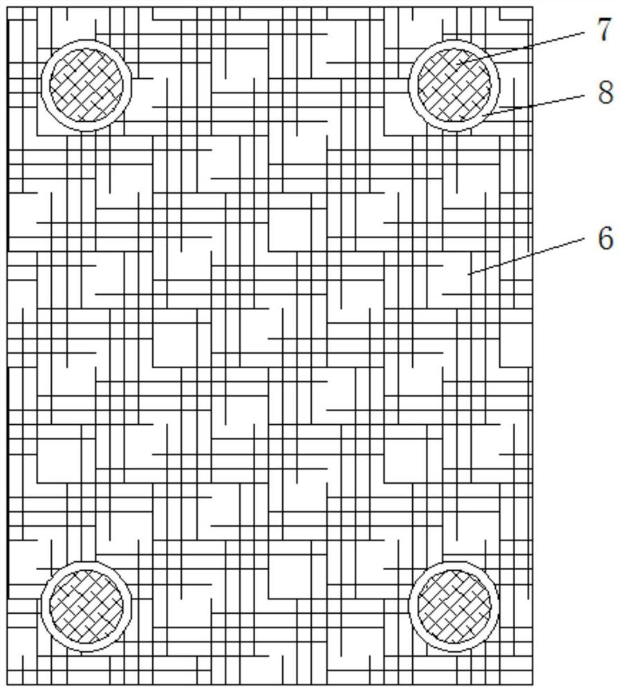
[0016] according to figure 1 , 2 , as shown, this embodiment proposes a protective layer structure for the display and control surface, including the display and control surface sticker 1, the glue layer 2, the waterproof drying layer 3, the corrosion-resistant layer 4, the wear-resistant layer 5 and the high-temperature resistant layer 6 , a waterproof drying layer 3 is provided above the display control surface sticker 1, and positioning bosses 7 are symmetrically arranged on the waterproof drying layer 3, and four sets of positioning bosses 7 are arranged on the waterproof drying layer 3. There is a corrosion-resistant layer 4, a wear-resistant layer 5 is arranged above the corro...


PUM

PropertyMeasurementUnit
thicknessaaaaaaaaaa
thicknessaaaaaaaaaa
thicknessaaaaaaaaaa

Abstract

The invention discloses a display control surface patch protective layer structure which comprises a display control surface patch, gluing layers, a waterproof drying layer, a corrosion-resistant layer, a wear-resistant layer and a high-temperature-resistant layer. The waterproof drying layer is arranged above the display control surface patch, the corrosion-resistant layer is arranged above the waterproof drying layer, the wear-resistant layer is arranged above the corrosion-resistant layer, and the high-temperature-resistant layer is arranged above the wear-resistant layer. The display control surface patch, the waterproof drying layer, the corrosion-resistant layer, the wear-resistant layer and the high-temperature-resistant layer are connected through the gluing layers. By arranging the waterproof drying layer, the display screen part in the display control surface patch can be prevented from generating water mist to influence observation of the display screen. The service life ofthe display control surface patch in a corrosive gas environment can be prolonged through the corrosion-resistant layer. Abrasion caused by touching or pressing the display control surface patch can be reduced through the abrasion-resistant layer. The high-temperature-resistant layer can prevent the display control surface patch from deforming in a high-temperature environment, so that the servicelife of the display control surface patch is prolonged.

Description

technical field [0001] The invention relates to the technical field of display and control surface stickers, in particular to a protective layer structure of display and control surface stickers. Background technique [0002] The control panel is the medium for interaction and information exchange between the system and the user. It realizes the conversion between the internal form of information and the form acceptable to humans. Nowadays, the control panel has been widely used in mechanized equipment, intelligent control equipment, household appliances, etc. fields with broad prospects. The display and control surface sticker in the control panel is one of its main components. The display and control surface sticker can mark some function keys and indicators on the control panel. When using the display and control panel, it is necessary to touch or press the display and control surface Such a long-term use will cause damage to the display and control surface stickers, and...

Claims


Application Information

Patent Timeline
Patent Type & Authority Applications(China)
IPC IPC(8): B32B27/32B32B27/30B32B27/36B32B27/08B32B27/06B32B3/08B32B3/24B32B7/12
CPCB32B27/32B32B27/304B32B27/302B32B27/322B32B27/365B32B27/08B32B27/06B32B3/08B32B3/266B32B7/12B32B2457/20B32B2307/554B32B2307/714B32B2307/306
Inventor 陈学兵徐云鸿张信群何韵
Owner 滁州英诺信电器有限公司
Learn More