Lens cone mold

A technology of mold and lens barrel, which is applied in the field of lens preparation, can solve the problems that the runner cannot be set in the mold opening direction of the slider, and the mold structure is complex, so as to achieve the effects of saving molding raw materials, simple structure and composition, and improving productivity

Inactive Publication Date: 2021-01-05
JIANGXI JINGCHAO OPTICAL CO LTD
View PDF0 Cites 0 Cited by
  • Summary
  • Abstract
  • Description
  • Claims
  • Application Information

AI Technical Summary

Problems solved by technology

[0005] Based on this, it is necessary to provide a lens barrel mold for the problem that the flow channel cannot be set along the mold opening direction of the slider during the mold opening process, which makes the overall mold structure more complicated.

Method used


Image

  • Lens cone mold
  • Lens cone mold
  • Lens cone mold

Examples


Embodiment Construction

[0070] In order to make the above objects, features and advantages of the present invention more comprehensible, specific implementations of the present invention will be described in detail below in conjunction with the accompanying drawings. In the following description, numerous specific details are set forth in order to provide a thorough understanding of the present invention. However, the present invention can be implemented in many other ways different from those described here, and those skilled in the art can make similar improvements without departing from the connotation of the present invention, so the present invention is not limited by the specific embodiments disclosed below.

[0071] It should be noted that when an element is referred to as being “fixed” to another element, it can be directly on the other element or there can also be an intervening element. When an element is referred to as being "connected to" another element, it can be directly connected to t...


PUM


Abstract

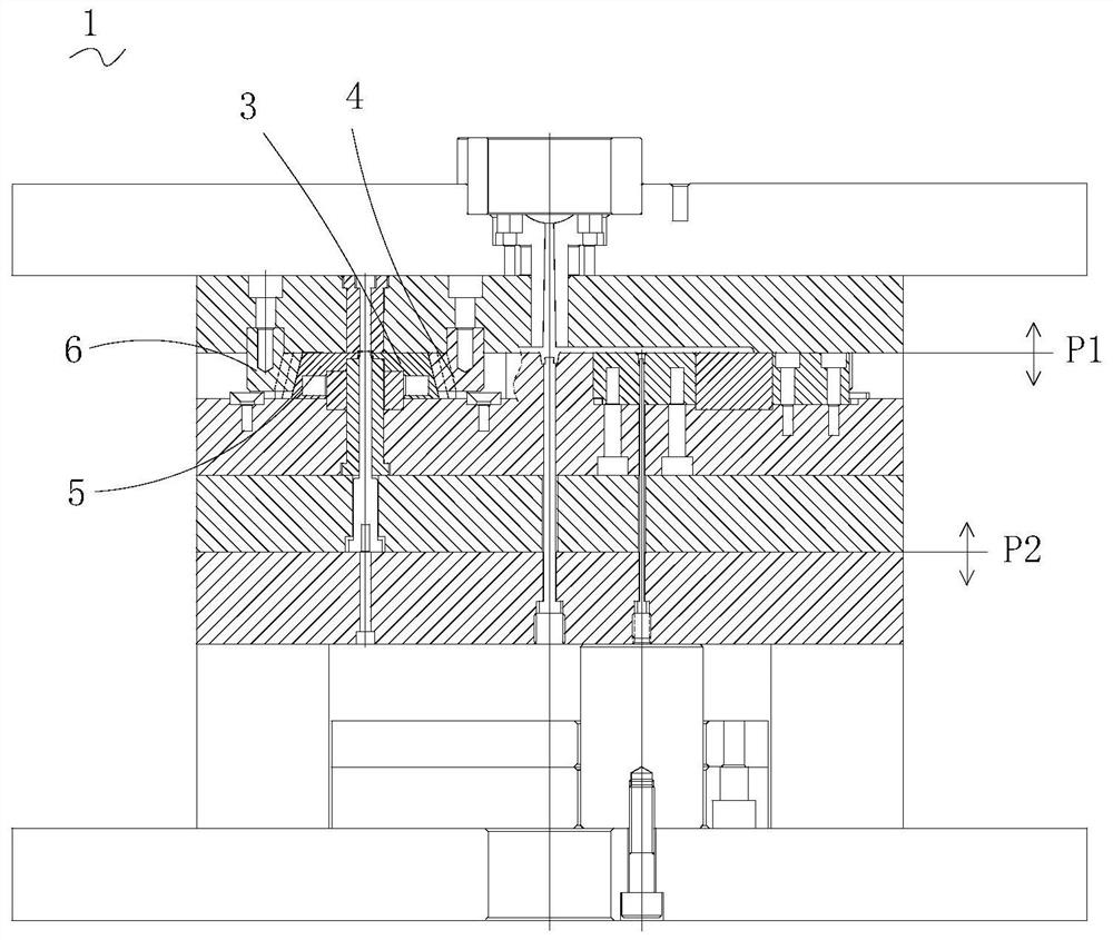
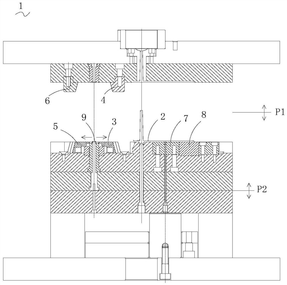
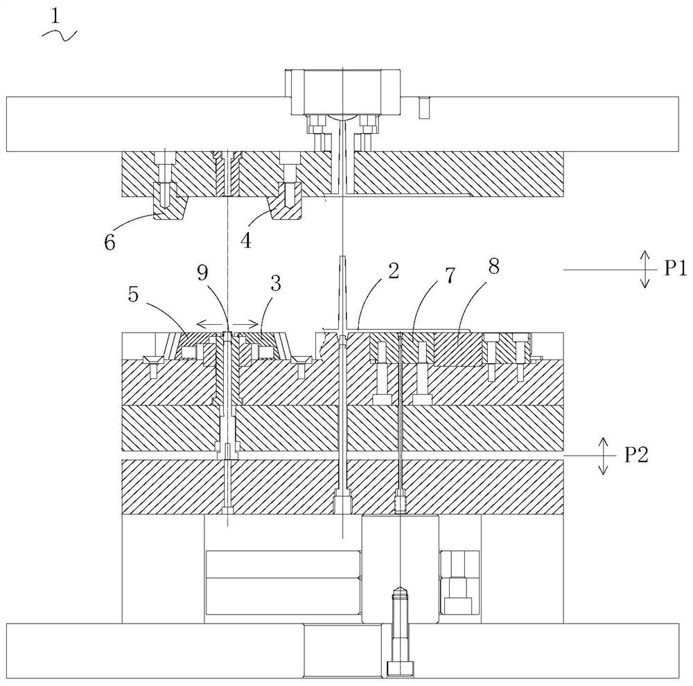
The invention relates to a lens cone mold. The lens cone mold comprises a female mold set, a male mold set matched with the female mold set and a push-out mechanism matched with the male mold set. Theabutted surface of a female mold sleeve plate and a male mold sleeve plate is defined as a first parting surface, and the abutted surface of the male mold sleeve plate and a male mold fixing plate isdefined as a second parting surface; a female mold cavity, a male mold cavity and a slide block group jointly define a product mold cavity; and the projection of a sub-runner on the first parting surface is overlapped with the projections of a locking block group and the slide block group on the first parting surface. The mold has the technical effects that when the mold is opened on the first parting surface, a product is left on one side of the male mold sleeve plate, the product is prevented from adhering to the female mold sleeve plate during mold opening; and when the mold is opened on the second parting surface, the sliding block group moves relative to the locking block group, so that the mold opening process is completed. The sub-runner can be arranged in a mold opening release direction of the slide block group and is not influenced by the mold opening release direction of the slide block group.

Description

technical field [0001] The invention relates to the technical field of lens preparation, in particular to a lens barrel mold. Background technique [0002] The optical lens includes a lens barrel and a lens group installed in the lens barrel, and the lens group includes a plurality of lenses. The light enters from the object-side end surface of the lens barrel, passes through the lens group, and enters the photosensitive chip through the image-side end surface of the lens barrel, thereby realizing imaging. Usually, the lens barrel is prepared by injection molding. [0003] Such as Figure 1 to Figure 3 As shown, in the traditional lens barrel mold 1, a main flow channel is provided on the female mold cover plate, and a runner 2 is provided on the side of the female mold cover plate facing the male mold cover plate, through which the pouring liquid is introduced into the mother mold cover plate. In the product cavity formed after the mold set plate and the male form set pla...

Claims


Application Information

Patent Timeline
IPC IPC(8): B29C45/26B29C45/33B29C45/44B29C45/27B29C45/66B29L11/00
CPCB29C45/26B29C45/2602B29C45/27B29C45/33B29C45/4435B29C45/66B29L2011/00
Inventor 张刚强邹海荣杨文明
Owner JIANGXI JINGCHAO OPTICAL CO LTD
Why Eureka
Try Eureka