Pipe liner internal aligning device system
A technology of internal counterpart and liner, which is applied in the field of pipeline gasket internal counterpart system, which can solve the problems of long auxiliary matching time, low service life and low matching precision, so as to improve service life, reduce matching time and ensure matching The effect of precision
- Summary
- Abstract
- Description
- Claims
- Application Information
AI Technical Summary
Problems solved by technology
Method used
Image
Examples
Embodiment 1
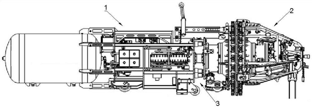
[0049]Such asfigure 1 As shown, the present invention discloses a pipe liner internal counterpart system, including a fuselage system 1, a cone system 2, and also a flexible connecting system 3; the flexible connecting system 3 includes a connecting machine The universal joint 31 of the body system (1) and the cone system 2.
[0050]In this solution, the flexible connection system 3 is set to change the rigid connection method of the traditional pipe liner, and the fuselage system 1 and the cone system 2 are connected through the flexible connection system 3 to realize the fuselage system 1 and the cone system The flexible connection of 2, through the setting of flexible connection system 3, allows the position and angle of the cone system 2 relative to the fuselage system 1, which greatly improves the accuracy of the alignment and the coaxiality of the cone system and the steel pipe after the alignment. The service life problem caused by the rigid connection of the cone system 2 and t...
Embodiment 2
[0052]Such asFigure 2-5 As shown, on the basis of Example 1, the present invention is further limited.
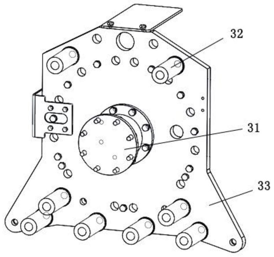
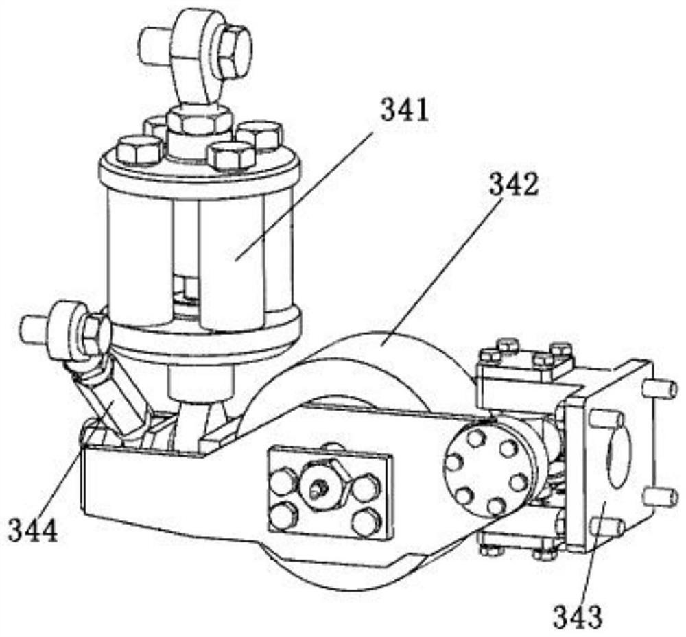
[0053]The flexible connecting system 3 further includes a first elastic connecting member 32, a connecting plate 33, and at least two front wheel flexible systems 34; the universal joint 31 is connected to the cone system 2 through the connecting plate 33; the first elastic connecting member 32 One end is connected to the connecting plate 33, and the other end is connected to the fuselage system 1. The arrangement of the connecting plate 33 and the first elastic connecting member 32 further ensures the flexible connection strength of the fuselage system 1 and the cone system 2; The arrangement of the connecting piece 32, due to the elasticity of the first elastic connecting piece 32, ensures that the position and angle deviation of the cone system 2 and the fuselage system 1 due to the pipe shape can be under the elastic action of the first elastic connecting piece 32 The quick reco...
Embodiment 3
[0062]Such asFigure 6-10 As shown, on the basis of Example 1, the present invention is further limited.
[0063]The cone system 2 includes a first expansion cylinder 21, a second expansion cylinder 22, and a gasket 23; the first expansion cylinder 21 and the second expansion cylinder 22 can be pressed against the inner surface of the pipe under the action of expansion force; The first expansion cylinder 21 is closer to the fuselage system than the second expansion cylinder 22. By arranging the first expansion cylinder 21 and the second expansion cylinder 22, the relative positions of the two pipes during pipe welding are ensured. In the pipeline welding type, the top of the first expansion cylinder 21 contacts the inner surface of one of the pipes to be welded. The second expansion cylinder top 22 extends to contact the inner surface of another pipe to be welded to realize the connection between the welded pipes; the gasket 23 is arranged between the first expansion cylinder 21 and the...
PUM
 Abstract
Description
Claims
Application Information
 - R&D
- Intellectual Property
- Life Sciences
- Materials
- Tech Scout
- Unparalleled Data Quality
- Higher Quality Content
- 60% Fewer Hallucinations
Browse by: Latest US Patents, China's latest patents, Technical Efficacy Thesaurus, Application Domain, Technology Topic, Popular Technical Reports.
© 2025 PatSnap. All rights reserved.Legal|Privacy policy|Modern Slavery Act Transparency Statement|Sitemap|About US| Contact US: help@patsnap.com


