
Sweeping robot

A sweeping robot and rack technology, applied in the field of sweeping robots, can solve problems such as high cost, damage to the connection structure of the lifting plate, and increased cleaning burden, and achieve the effects of preventing damage, saving installation space, and improving compactness

Active Publication Date: 2021-01-05
合肥哈工澳汀智能科技有限公司
View PDF12 Cites 4 Cited by
  • Summary
  • Abstract
  • Description
  • Claims
  • Application Information

AI Technical Summary

Problems solved by technology

The sweeping robot disclosed in this application document avoids obstacles through sensors, and it is difficult to clean the ground behind obstacles, which is not only costly, but also inconvenient to use
[0005] For example, the comparative document whose publication number is CN105433879B discloses a cleaning robot that uses a rolling brush to continuously rotate to make the garbage enter the garbage container for cleaning. Although this traditional cleaning efficiency is high, the cleaning effect is poor, and the cleaning effect is poor. On the ground, dust is raised, and when cleaning large-scale sites, especially when cleaning shopping malls or airports or railway station platform squares, large-scale sprinklers will not be used, and the dust treatment will not be effectively solved, and large-scale Garbage and small garbage are all processed together, resulting in increased cleaning burden and poor cleaning effect
[0006] The comparison document with the publication number CN205054052U discloses a floating quick-change side brush mechanism for sweeping vehicles. It is specifically disclosed that when the oil cylinder pushes away the rotating fixed block, the roller gradually leaves the lifting plate, and the AD section rotates downward along point A. , The brush body relies on its own gravity to act on the ground to form a cleaning job. Obviously, the comparison document uses a rigid connection method. When the side brush encounters a bumpy ground, it will cause certain damage to the connection structure of the lifting plate.

Method used


Image

  • Sweeping robot
  • Sweeping robot
  • Sweeping robot

Examples


Embodiment Construction

[0087] In order to facilitate those skilled in the art to understand the technical solution of the present invention, the technical solution of the present invention will be further described in conjunction with the accompanying drawings.

[0088] The terms "first" and "second" are used for descriptive purposes only, and cannot be understood as indicating or implying relative importance or implicitly specifying the quantity of indicated technical features. Thus, a feature defined as "first" and "second" may explicitly or implicitly include one or more of these features. In the description of the present application, "plurality" means two or more, unless otherwise specifically defined.

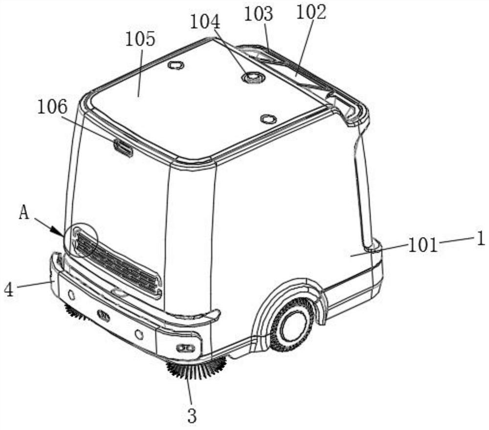
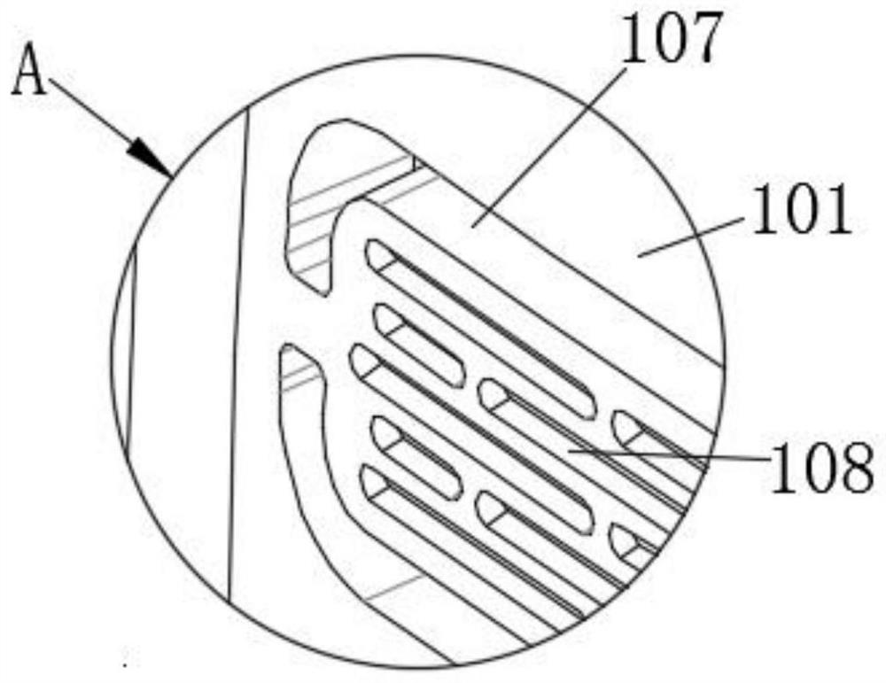
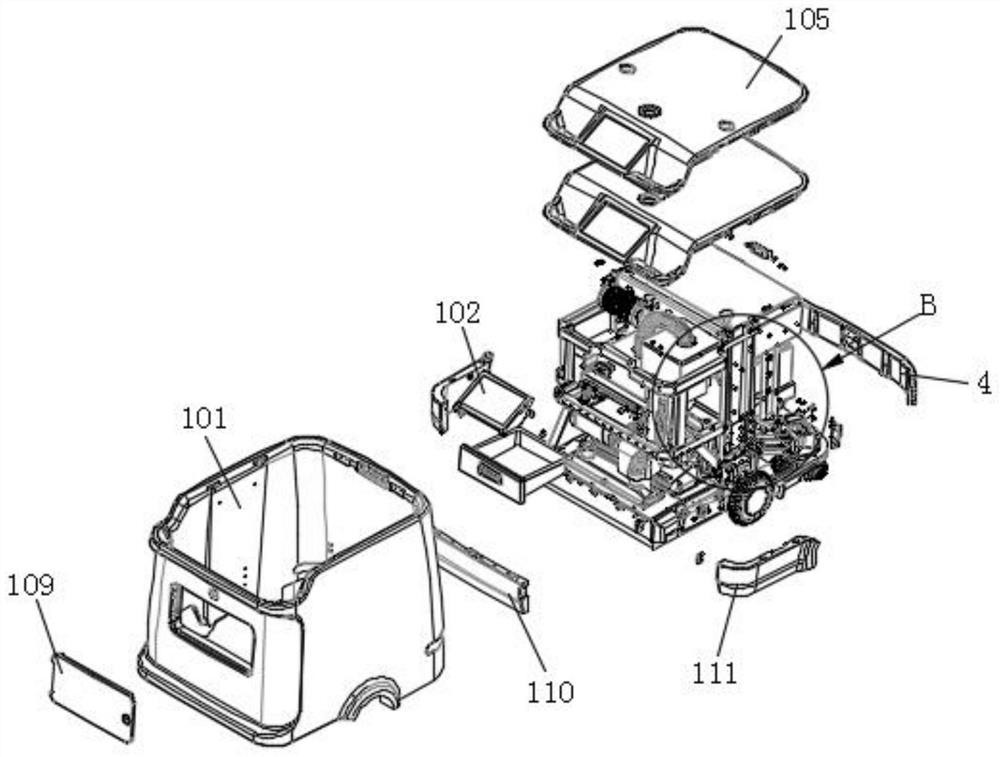
[0089] refer to figure 1 and 7 , this embodiment discloses a sweeping robot, including a casing 1 and a frame assembly 9 ; the frame assembly 9 includes a main beam 901 . The length of the main beam 901 is the same as the width direction of the cleaning robot. The two ends of the main beam ...


PUM


Abstract

The invention discloses a sweeping robot which comprises a main brush assembly, a rack assembly and a side brush assembly. The side brush assembly and the main brush assembly are connected to the front end and the rear end of the rack assembly respectively. The main brush assembly comprises a main brush lifting assembly and a main brush roller. The main brush lifting assembly comprises a main brush steel wire rope and a main brush air cylinder. The main brush roller is connected to the output end of the main brush air cylinder through a flexible main brush steel wire rope. The side brush assembly comprises a side brush lifting structure and a side brush connecting piece. The side brush lifting structure comprises a side brush steel wire rope and a side brush cylinder; one end of the side brush connecting piece is rotationally connected to the rack assembly. The other end of the side brush connecting piece is connected to the output end of the side brush air cylinder through the flexible side brush steel wire rope. According to the invention, when the main brush assembly and the side brush assembly sweep bumpy ground, the robot is lifted, and the main brush steel wire rope becomes loose, so that damage to parts is reduced.

Description

technical field [0001] The invention relates to the technical field of sweeping robots, in particular to a sweeping robot. Background technique [0002] Sweeping robot is a kind of machine equipment used to clean the ground. The low-cost sweeping robot uses rotating walking wheels to clean the place. Its cleaning track is an arc track. When encountering obstacles, the sweeping robot is blocked and no longer moves towards the obstacle until the walking wheels rotate to another direction. The sweeping robot continues to work when it is in the opposite direction to achieve "obstacle avoidance". However, some obstacles are slightly higher than the ground by 0.5-2cm, which can be completely crossed. Not good; expensive robots can sense obstacles by setting various sensors, and then achieve "obstacle avoidance". It is completely unnecessary to choose to avoid, and the sweeping robot has a wide variety of sensor settings and a complex structure, and the installation structure of ...

Claims


Application Information

Patent Timeline
IPC IPC(8): A47L11/24A47L11/40
CPCA47L11/24A47L11/40A47L11/4038A47L11/4027A47L11/4008A47L11/4069A47L11/4077A47L2201/00
Inventor 赵子建周奎张伟汪伟于振中李文兴
Owner 合肥哈工澳汀智能科技有限公司
Learn More