Composite electrical contact

An electrical contact, composite technology, applied in the direction of contacts, circuits, electrical switches, etc., can solve problems such as insignificant effects, and achieve the effect of eliminating contact bounce and improving elastic deformation capacity.

Active Publication Date: 2021-01-01
山东晨鸿电气有限公司
View PDF3 Cites 0 Cited by
  • Summary
  • Abstract
  • Description
  • Claims
  • Application Information

AI Technical Summary

Problems solved by technology

However, the effect of these schemes is not obvious at the high closing speed of the fast switch

Method used


Image

  • Composite electrical contact
  • Composite electrical contact
  • Composite electrical contact

Examples


Embodiment 1

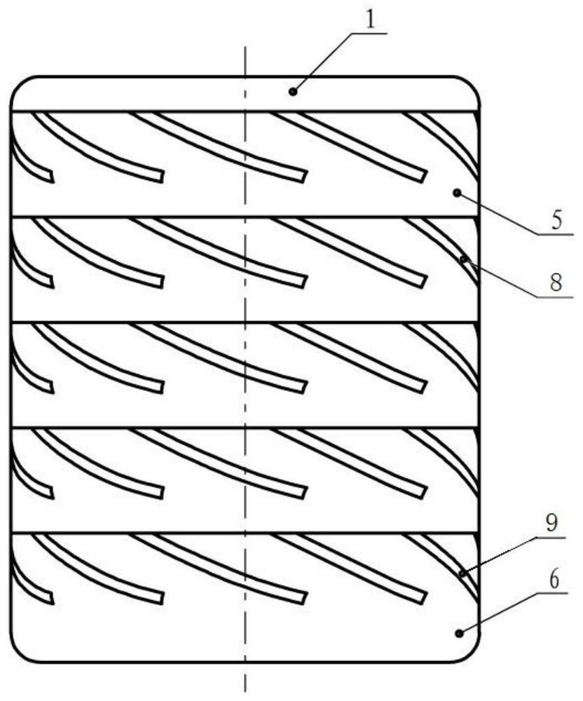
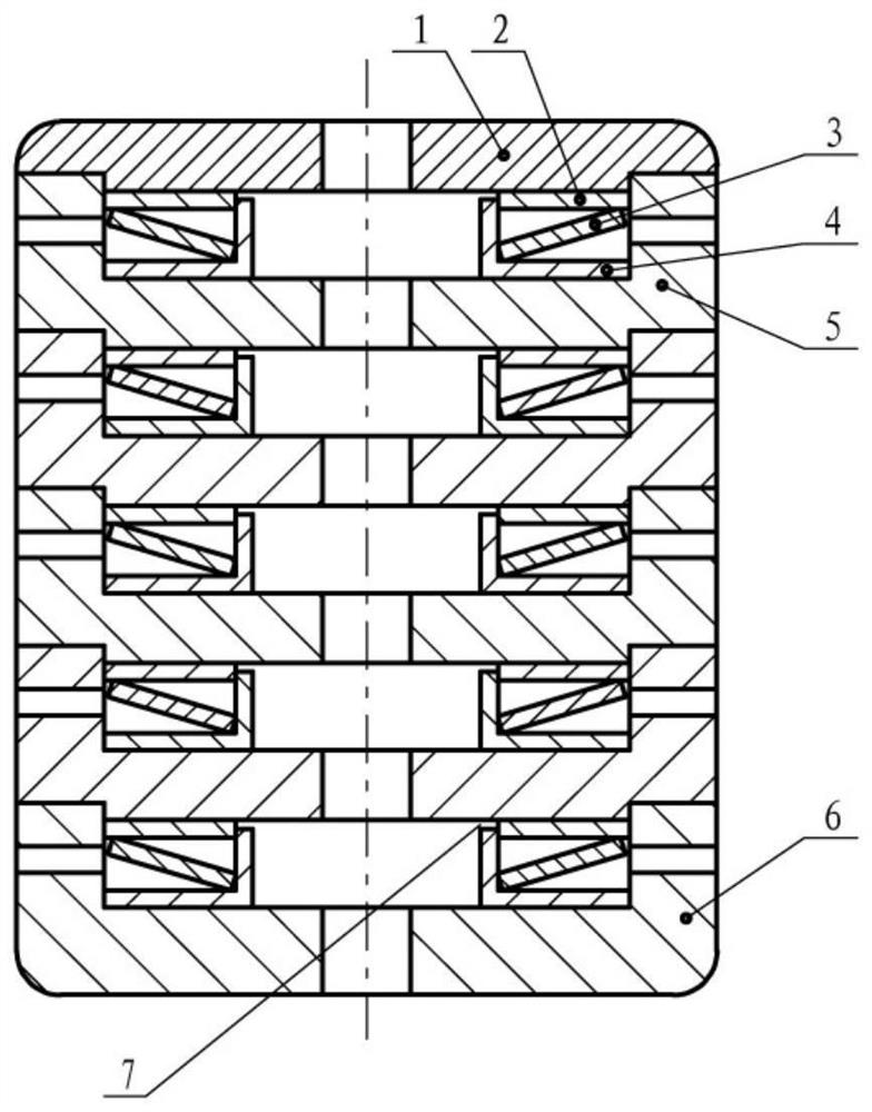
[0034] Such as Figure 1-3 As shown, the composite electrical contact includes successively arranged contact pieces 1, at least one middle cup holder 5, and a rear cup holder 6, and the inner cavity of the middle cup holder 5 and the tail cup holder 6 All are provided with an elastic support structure, the elastic support structure includes a positioning washer 4, and the positioning washer 4 passes through the disc washer 3 and the support washer 2 in turn, and the support washer 2 is arranged in the contact sheet 1 and the center Place the lower surface of the cup holder 5, the positioning gasket 4 is arranged on the upper surface of the central cup holder 5 and the tail cup holder 6, the upper surface of the positioning gasket 4 is connected with the contact piece 1 and the lower surface of the central cup holder 5 There is a stop gap 7.

[0035] The disk washer 3 in the elastic support structure is compressed to generate a rebound force opposite to the direction of motion...

Embodiment 2

[0064] The difference with embodiment 1 is:

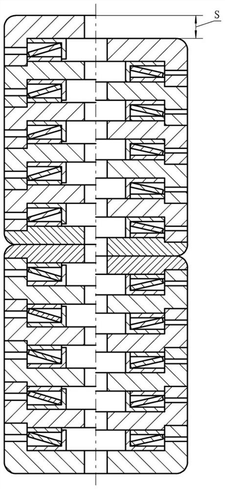
[0065] Such as Figure 4-5 As shown, in order to reduce the mass of the moving part of the vacuum interrupter and reduce the kinetic energy, the moving-end composite electrical contact and the static-end composite electrical contact adopt different configurations. Specifically, the contact piece 1, the middle cup holder 5 and the tail cup holder 6 of the moving-end compound electric contact are all one; the contact piece 1 and the tail cup holder 6 of the static-end composite electric contact All are 1, and the center cup holder 5 is 2. Each of the central cup holder 5 and the rear cup holder 6 is provided with a support gasket 2, a dish washer 3, a positioning gasket ring 4, and a stop gap 7 each.

[0066] In this embodiment, the closing speed of the fast switch is v=1.6m / s, the contact pressure is f=2500N, and the mass of the moving part of the vacuum interrupter is m=0.5kg. From the acceleration formula f=ma, calculate a=5000...


PUM


Abstract

The invention relates to a composite electrical contact, and belongs to the technical field of power switch equipment. The composite electric contact comprises a contact piece, at least one middle cupbase and a tail cup base which are arranged in sequence, elastic supporting structures are arranged in inner cavities of the middle cup base and the tail cup base, each elastic supporting structure comprises a positioning backing ring, and the positioning backing rings sequentially penetrate through a dish-shaped gasket and a supporting gasket. The supporting gasket is arranged on the lower surfaces of the contact blade and the middle cup base, the positioning backing ring is arranged on the upper surfaces of the middle cup base and the tail cup base, and a stop gap is reserved between the upper surface of the positioning backing ring and the lower surfaces of the contact blade and the middle cup base. Impact force of the contact during closing of the quick switch can be absorbed througha buffering effect, and closing bounce of the contact is eliminated.

Description

technical field [0001] The invention relates to a composite electric contact, which belongs to the technical field of power switching equipment. Background technique [0002] When the vacuum switch, especially the medium and high voltage fast switch, is closed, because the contacts of the traditional vacuum interrupter are in rigid plane contact, the moving contact will rebound multiple times after hitting the static contact, and the amount of rebound will gradually attenuate. Finally, the contact Fully closed, this process is called contact bouncing, and the time from the moment the contact is first touched to fully closed is called the contact closing bounce time. The large bounce amplitude reduces the fatigue life of the bellows, which in turn leads to a sharp shortening of the vacuum life of the vacuum interrupter. A long bounce time will cause the arc heat to accumulate between the contacts, resulting in aggravated contact surface burns, and more likely to cause contact...

Claims


Application Information

Patent Timeline
IPC IPC(8): H01H33/664H01H1/50
CPCH01H33/664H01H1/50
Inventor 刘永飞谢国良滕师勇
Owner 山东晨鸿电气有限公司
Why Eureka
Try Eureka