
A large-scale underwater explosion damage test system and method

A technology of underwater explosion and test system, which is applied in the field of theoretical analysis of underwater explosion and damage. The effect of error and safety universality

Inactive Publication Date: 2021-06-08
BEIJING INSTITUTE OF TECHNOLOGYGY +2
View PDF3 Cites 0 Cited by
  • Summary
  • Abstract
  • Description
  • Claims
  • Application Information

AI Technical Summary

Problems solved by technology

[0004] The disadvantages of this test plan are: firstly, when the target and the detonation source are dragged into the designated waters, the detonating tube is affected by drag force and resistance, coupled with environmental factors such as sea wind and waves, and the connection stability is easily damaged, which may lead to The connection is unstable or even falls off, so that the test cannot be completed normally; secondly, there is no fixation to the test platform in the existing test, and the test device may rotate or shift under the influence of environmental factors, resulting in errors in test data collection, which greatly Affects the accuracy of the test; in addition, when the detonating tube is arranged in the existing test, it is directly dragged, and the detonating tube is directly stressed and easily damaged, which may cause a delay in detonation time or even failure to detonate, which is bad for the completion and accuracy of the test influences
[0005] It can be seen that when the existing technology conducts underwater explosion damage tests in large water areas, there are deficiencies in the overall plan of the test, the design of the operation process, the layout and fixation of the test platform, and the protection of the detonation system. Reliability has a significant impact on

Method used


Image

  • A large-scale underwater explosion damage test system and method
  • A large-scale underwater explosion damage test system and method
  • A large-scale underwater explosion damage test system and method

Examples


Embodiment Construction

[0034] The present invention will be described in detail below with reference to the accompanying drawings and examples.

[0035] The present invention provides a large-scale underwater explosion damage test scheme, which proposes solutions to several prominent problems in the prior art, specifically including:

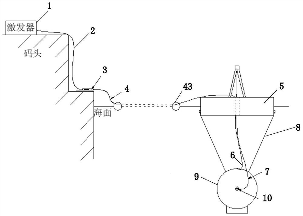
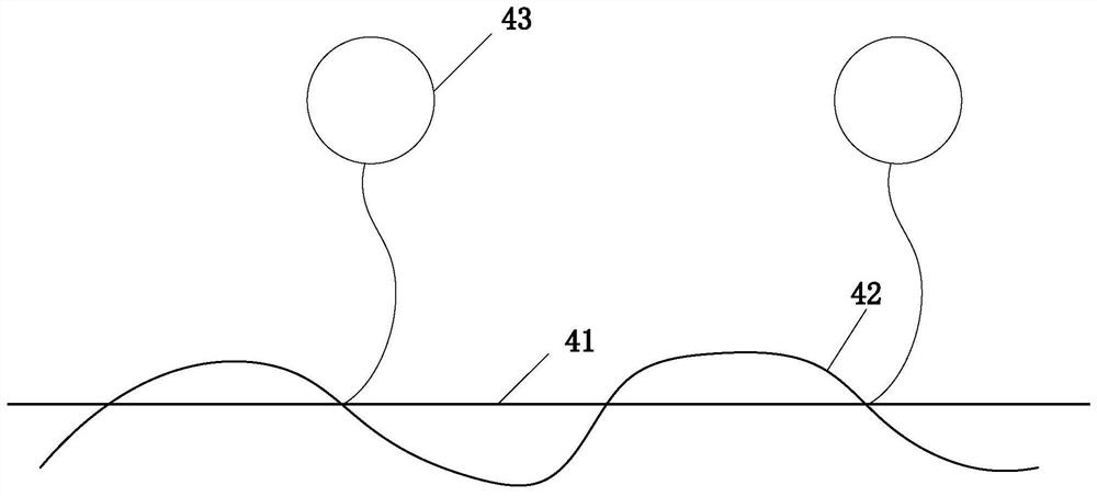
[0036] (1) During the test process, it is necessary to push the detonating tube to the detonation position on the water surface. The detonating tube is directly subjected to force and is easily damaged, which may cause a delay in detonation time or even failure to detonate, which has a negative effect on the completion and accuracy of the test. influences. Aiming at this problem, the present invention connects a strengthening cable to the detonating tube, replaces the detonating tube to be directly stressed during laying and dragging, thereby playing a protective role, and at the same time connects a floating ball to prevent sinking.

[0037] (2) There is no fixation...


PUM


Abstract

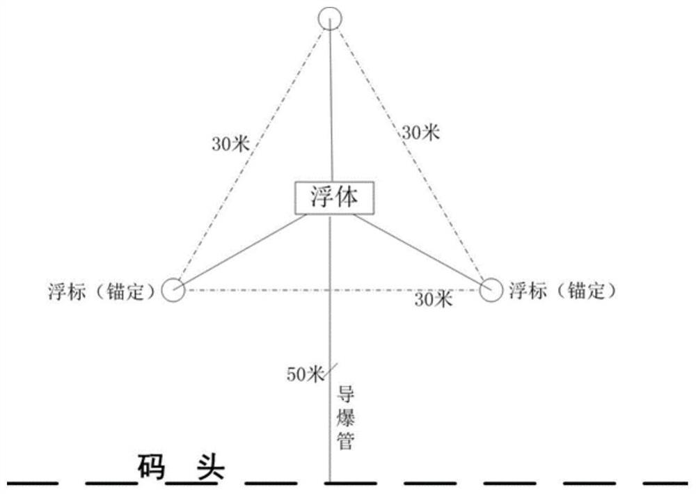
The invention discloses a large-scale water area underwater explosion damage test system and method. In the system, a floating body is located at a designated detonation point in the water area, and anchor buoys are arranged at three equidistant points around them, and the anchor buoys are connected to the floating body. Prevent the floating body from moving and rotating; the floating body is connected to the target through the lifting steel cable and the load-bearing steel cable; the lifting steel cable is controlled by the lifting mechanism on the floating body to realize the discharge and recovery of the target; the load-bearing steel cable includes at least 2 for fixing The relative position of the target and the floating body; the length of the load-bearing steel cable is set according to the specified detonation depth, and the unloading is stopped when the load-bearing steel cable is stressed during the discharge of the target; one end of the restricted detonating cord is fixed on the floating body, and the other end passes through the booster The column is connected to the test detonating source set on the target; the detonating system is connected to the restricted detonating cord on the floating body through the reinforced detonating tube. Using the present invention can improve the overall safety and reliability of the test.

Description

technical field [0001] The invention belongs to the technical field of theoretical analysis of underwater explosion and damage, and in particular relates to an underwater explosion damage test system and method for large water areas such as seas (lakes). Background technique [0002] With the rapid development of underwater weapons, the underwater explosion test of ammunition, as an important research method, is gradually systematized in practice. For underwater explosion damage tests, most of them are done in wells, pools or tanks. The test environment is relatively limited, which also limits the scale and accuracy of the test to a certain extent. In order to more realistically simulate the actual combat environment, it is necessary to carry out experiments in large waters such as seas (lakes). [0003] When carrying out experiments in large-scale waters, most of the existing test procedures are to connect the target to the detonation source on the shore, and then connect ...

Claims


Application Information

Patent Timeline
Patent Type & Authority Patents(China)
IPC IPC(8): F42B35/00
CPCF42B35/00
Inventor 王树山高源卢熹李兵金辉田恒斗张静骁贾曦雨郭策安
Owner BEIJING INSTITUTE OF TECHNOLOGYGY
Learn More