Cement-free pervious concrete brick

A permeable concrete, cement-free technology, used in climate change adaptation, roads, pavements paved with prefabricated blocks, etc., can solve the problem that the urban heat island effect cannot be effectively reduced, the rainwater cannot be trapped on the road surface, and the permeable bricks can penetrate quickly. problems, to reduce the urban heat island effect, avoid excessive pressure damage, and reduce the effect of pressure

Inactive Publication Date: 2021-01-01
陈浩
View PDF10 Cites 0 Cited by
  • Summary
  • Abstract
  • Description
  • Claims
  • Application Information

AI Technical Summary

Problems solved by technology

[0005] In order to make up for the deficiencies of the existing technology and solve the problem that the existing permeable bricks are too fast to retain rainwater on the road surface for evaporative cooling of the road surface in hot weather, the permeable pavement cannot effectively reduce the urban heat island effect. Cementless permeable concrete brick

Method used


Image

  • Cement-free pervious concrete brick
  • Cement-free pervious concrete brick
  • Cement-free pervious concrete brick

Examples


Embodiment approach

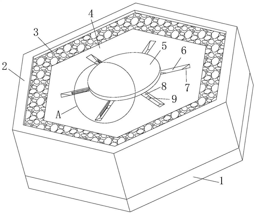
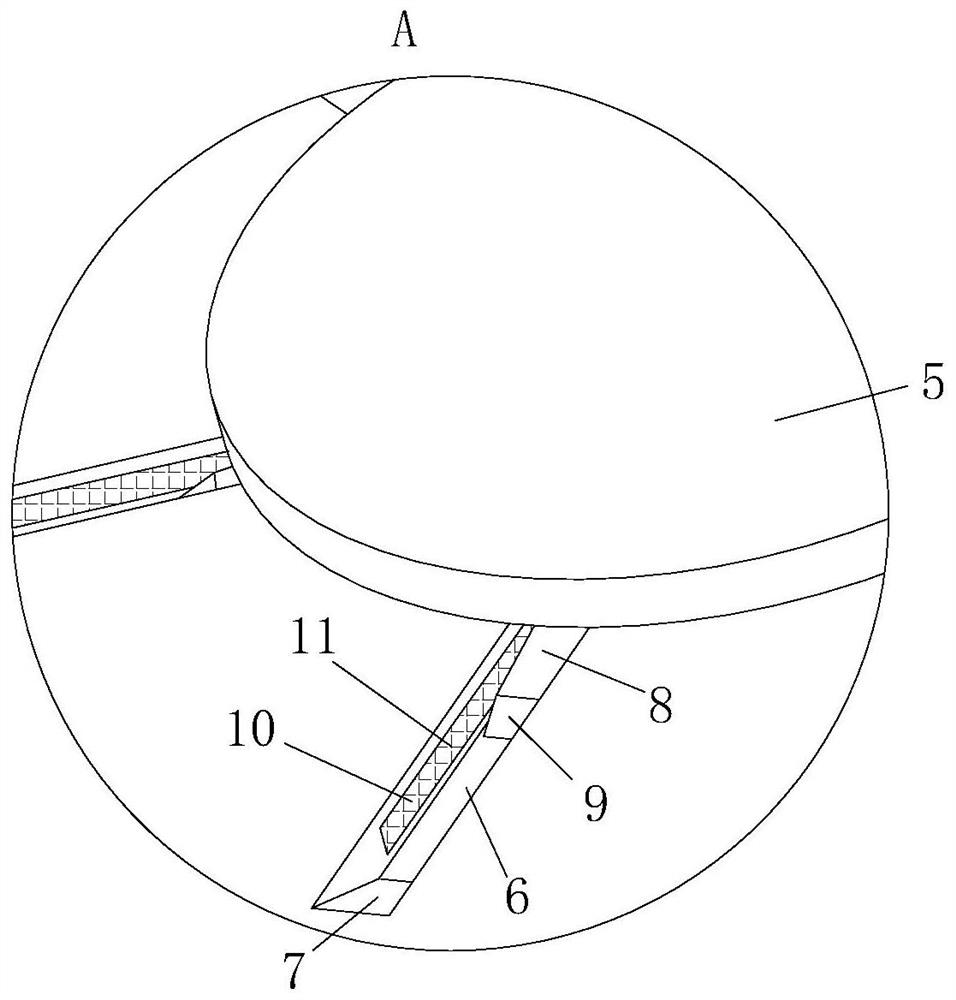
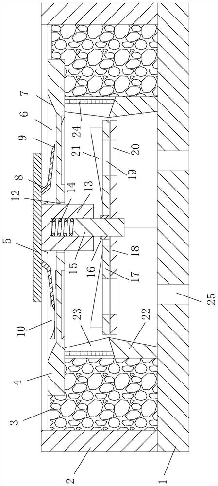
[0034] As a specific embodiment of the present invention, the side wall of the strip groove 6 is provided with a downward spirally extending water inlet hole 10, and the water inlet hole 10 communicates with the strip groove 6 and the inner cavity of the annular support cylinder 22 , the first filter screen 11 matching the water inlet hole 10 is arranged in the strip groove 6 . Since the permeable concrete block 3 is permeable drainage, when the rainfall is large, it will not be able to drain water in time and cause water accumulation on the panel 4. Therefore, through the setting of the water inlet 10, the accumulation of water on the panel 4 can be reduced. It is collected through the strip groove 6 and enters the inner cavity of the annular support cylinder 22 from the water inlet 10, and finally discharged through the drainage hole 25, so that there will be no water accumulation on the road and the risk of urban waterlogging is reduced; the first filter screen 11 is set , ...

specific Embodiment approach

[0038] As a specific embodiment of the present invention, the vertical rod 15 at the upper end of the second disc 18 is provided with a shaft sleeve 16 that can rotate around the vertical rod 15, and the outer side of the shaft sleeve 16 is fixed with the first disc 17 , the radius of the first disc 17 is the same as that of the second disc 18 , and the lower end surface of the first disc 17 is in contact with the upper end surface of the second disc 18 . Since the water inlet hole 10 is helically arranged, the water flow entering from the water inlet hole 10 can impact the first disk 17 and make the first disk 17 rotate around the vertical rod 15 through the shaft sleeve 16, and then the first disk 17 will be rotated by the action of centrifugal force. The accumulated water on the disc 17 is thrown out so that it can better enter the overflow tank 23, which is beneficial to the collection of rainwater.

[0039] As a specific embodiment of the present invention, a torsion spri...


PUM


Abstract

The invention relates to the technical field of pervious concrete bricks, in particular to a cement-free pervious concrete brick which comprises a bottom plate and a frame vertically arranged along the periphery of the bottom plate, an annular supporting cylinder vertically extending upwards is arranged on the bottom plate in the frame, and a panel for blocking an opening in the upper end of the annular supporting cylinder is fixedly arranged at the upper end of the annular supporting cylinder; rainwater and surface runoff can be collected in the pervious concrete block lower than the overflowgroove through the panel, the pervious concrete and the annular supporting cylinder, the phenomenon of road surface water accumulation is avoided, the pressure of urban drainage equipment is reduced,and the risk of urban inland inundation is reduced; meanwhile, in hot days after raining, the stored water can be evaporated, the pavement temperature is reduced, pavement sensible heat emission is reduced, and the urban heat island effect is reduced.

Description

technical field [0001] The invention relates to the technical field of permeable concrete bricks, in particular to a cementless permeable concrete brick. Background technique [0002] In the process of urbanization, soil layers and lawns that can store and permeate water have been eradicated. Replace it with hard impermeable materials such as roof, asphalt, concrete stone slabs or cement bricks, so that rainwater cannot be effectively stored in the surface soil layer and cannot penetrate into the ground, increasing the surface runoff. Surface runoff and rainwater can only be discharged into nearby rivers and pools through the dotted ditches, drainage pipes, and stormwater pipes. During heavy rainfall, the river water rises, and the groundwater level rises. The urban underground water system and drainage ditches cannot drain the surface runoff formed by the heavy rainfall in time, resulting in urban flooding. [0003] In recent years, permeable concrete bricks have been wid...

Claims


Application Information

Patent Timeline
Patent Type & Authority Applications(China)
IPC IPC(8): E01C5/06E01C11/22
CPCE01C5/06E01C11/22E01C11/225Y02A30/60
Inventor 陈浩刘鹏
Owner 陈浩
Why Eureka
Try Eureka