Safety belt hanging bracket

A technology for hanging brackets and safety belts, which is applied to safety belts and life-saving equipment, etc., which can solve the problems that workers are inconvenient to move and work, and achieve the effects of increasing the scope of application, moving smoothly and stably, and facilitating operations

Active Publication Date: 2021-01-01
国网山东省电力公司建设公司 +2
View PDF6 Cites 3 Cited by
  • Summary
  • Abstract
  • Description
  • Claims
  • Application Information

AI Technical Summary

Problems solved by technology

[0005] Aiming at the deficiencies of the prior art, the present invention provides a safety belt suspension bracket, which solves the problem that workers are inconvenient to move and work on the suspension bracket

Method used


Image

  • Safety belt hanging bracket
  • Safety belt hanging bracket
  • Safety belt hanging bracket

Examples


Embodiment 1

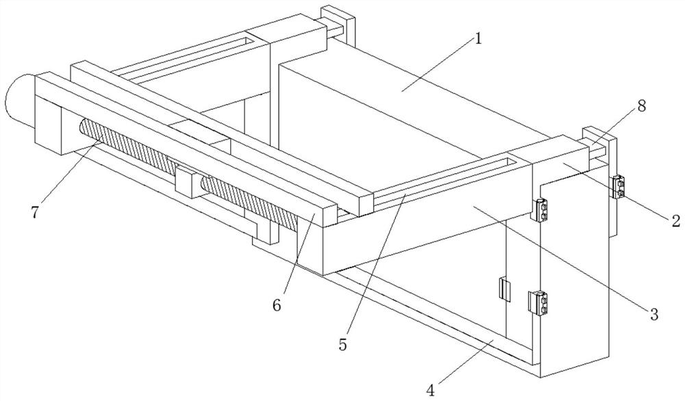
[0033] A seat belt suspension bracket such as Figure 1-Figure 6 As shown, including the wall 1, the surface of the wall 1 is connected with two support blocks 2 by bolts, the front parts of the two support blocks 2 are welded with a connection block 3, and a support is welded between the connection block 3 and the support block 2 Rod 4, the upper surface of connecting block 3 is provided with slide rail 5, and the inner wall of slide rail 5 is slidingly connected with two limiting plates 6, and the lower surface of limiting plate 6 is slidingly connected with the upper surface of connecting block 3, two A transmission mechanism 7 is arranged between the connecting blocks 3 , and a fixing mechanism 8 is arranged at the rear of the support block 2 .

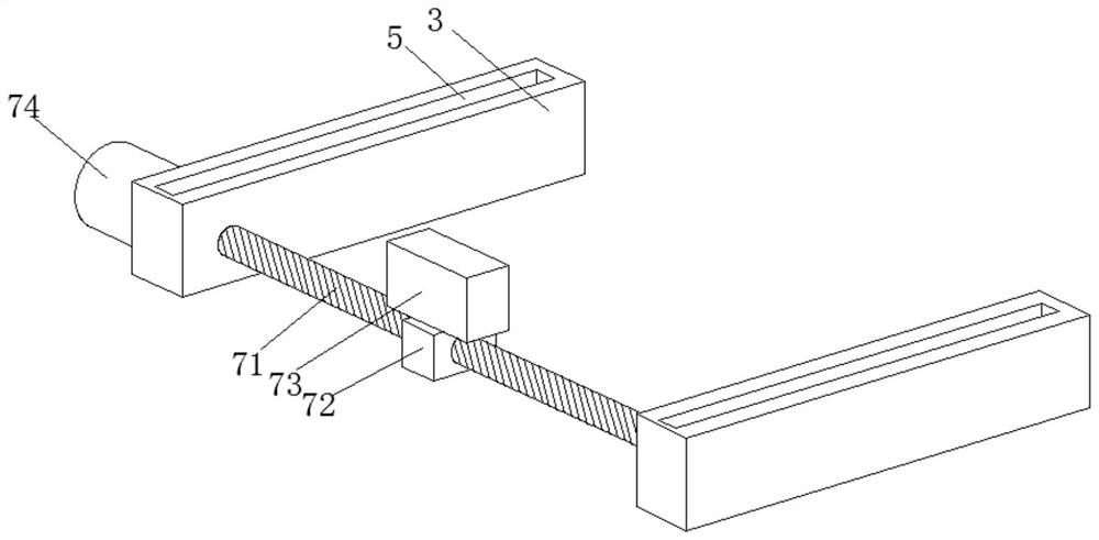
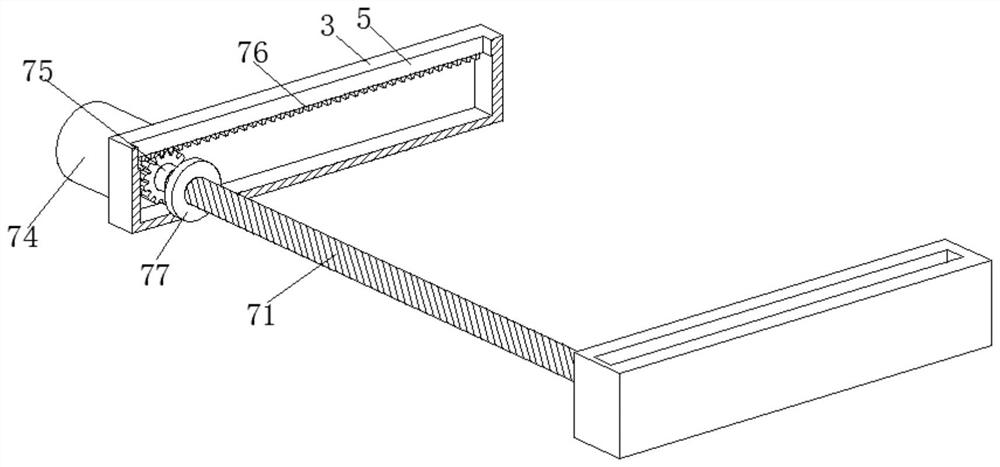
[0034] In this embodiment, the transmission mechanism 7 includes a screw rod 71, the surface of the screw rod 71 is threadedly connected with a moving block 72, the top of the moving block 72 is welded with a limit block 73, and t...

Embodiment 2

[0040] Such as Figure 5-Figure 7 As shown, the surface of the connecting plate 81 is slidingly connected with the inner wall of the support block 2, the rear end of the tension spring 84 is welded and fixed with the inner wall of the support block 2, and the front part of the fixed plate 82 is connected to the rear part of the body of wall 1 by bolts. The tension spring 84 will pull the connecting plate 81, so that the fixed plate 82 at the rear of the connecting plate 81 and the support block 2 tightly clamp the wall 1, which is convenient for workers to fix and install it with bolts, and reduces the workman's work. Labor intensity also increases the efficiency of installation.

[0041] It is worth noting that the installation device 83 includes a fixed block 831, the inner wall of the fixed block 831 is rotatably connected with a rotating shaft 832, the right side of the fixed block 831 is respectively rotatably connected with two rotating plates 833, and the right side of th...


PUM


Abstract

The invention relates to the technical field of buildings, and discloses a safety belt hanging bracket which comprises a wall body. Two supporting blocks are connected to the surface of the wall bodythrough bolts, connecting blocks are welded to the front portions of the two supporting blocks, supporting rods are welded between the connecting blocks and the supporting blocks, and a sliding rail is arranged on the upper surfaces of the connecting blocks. Two limiting plates are slidably connected to the inner walls of the sliding rail, a transmission mechanism is arranged between the two connecting blocks, and fixing mechanisms are arranged on the rear portions of the supporting blocks. Through cooperative use of the transmission mechanism and a moving device, a worker can conduct left-right and front-back moving operation, left-right movement is conducted through threads, the movement is gentler and more stable, the swing amplitude of workers can be reduced, potential safety hazards are reduced accordingly, the workers can adjust the distance between the workers and the wall according to needs through front-back movement, then the workers can conduct operation more conveniently, and the practicability is greatly improved.

Description

technical field [0001] The invention relates to the technical field of construction, in particular to a safety belt suspension bracket. Background technique [0002] As an extremely complex project, the construction of the construction industry does not require a long construction period, more manpower, and financial resources. It also needs the support of new technologies. In order to ensure the construction quality of the construction industry and realize the safe and stable operation of the project, construction technology must In order to solve the various problems that existed before, it is necessary to continuously innovate the construction technology of the construction industry. [0003] At present, when workers use safety belts to hang on the suspension bracket for work, the workers can only work on the area in front of them and cannot move, or it is very inconvenient to move, and they need to manually pull the rope to move, which is very dangerous. Therefore, a A ...

Claims


Application Information

Patent Timeline
Patent Type & Authority Applications(China)
IPC IPC(8): A62B35/00
CPCA62B35/0025
Inventor 王璐陈永辉王永顺曹东明张震安仲杰李东阳武帅朱瑞姬晟翔
Owner 国网山东省电力公司建设公司
Why Eureka
Try Eureka