
Camshaft, and method for the production of a camshaft

A technology of camshafts and sliding cams, which is applied in the field of manufacturing camshafts, can solve problems such as damage to axial displacement, and achieve the effects of simple device, easy manufacture, and good axial displacement

Active Publication Date: 2020-12-29
THYSSENKRUPP PRESTA TECCENTER AG +1
View PDF9 Cites 0 Cited by
  • Summary
  • Abstract
  • Description
  • Claims
  • Application Information

AI Technical Summary

Problems solved by technology

This can lead to impaired axial displacement

Method used


Image

  • Camshaft, and method for the production of a camshaft
  • Camshaft, and method for the production of a camshaft
  • Camshaft, and method for the production of a camshaft

Examples


Embodiment Construction

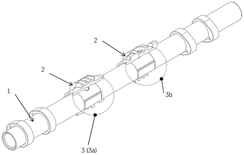
[0043] first reference figure 1 .

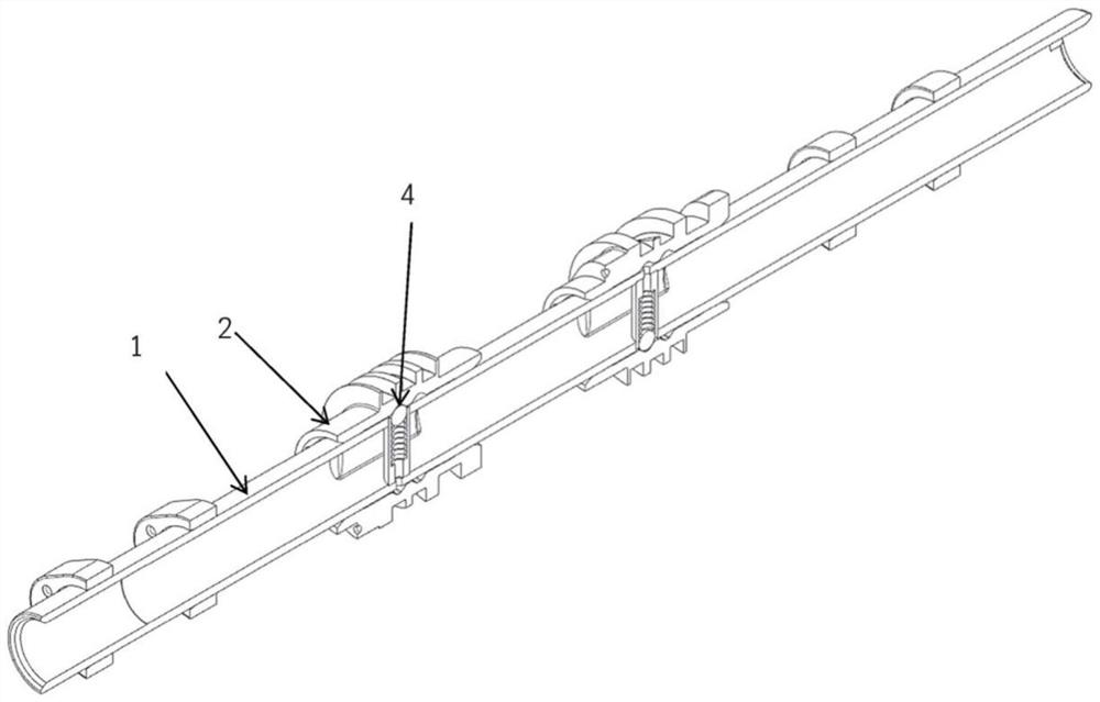
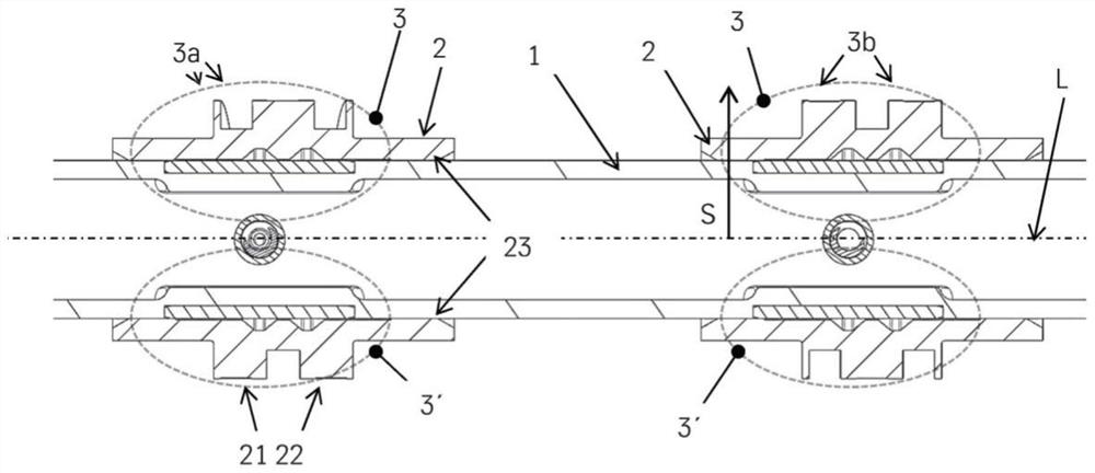
[0044] The camshaft according to the invention essentially comprises a shaft 1 and at least one sliding cam assembly 2 . The sliding cam assembly 2 is arranged on the shaft 1 in a rotationally fixed but axially movable manner. Arranged between the shaft 1 and the sliding cam assembly 2 is a device 3 for preventing rotation, wherein the device 3 for preventing rotation has a recess 33 facing the shaft 1 in the sliding cam assembly 2 and a sliding facing in the shaft 1 The flat portion 31 of the cam assembly and the intermediate element 32 arranged between the flat portion 31 and the notch 33 .

[0045] The shaft 1 is preferably designed as a hollow shaft with a circular cross section. The shaft 1 has a longitudinal axis L or an axis of rotation. Axis 1 can be equipped with other accessories and functional parts such as fixed cams, needle bearings, bearing rings, sensor wheels and ends.

[0046] The sliding cam assembly 2 preferably compris...


PUM


Abstract

The present invention relates to a camshaft, comprising a shaft (1) with a longitudinal axis (L) and at least one sliding cam pack (2), wherein the sliding cam pack (2) is arranged on the shaft (1) fixedly so as to rotate with it but in an axially displaceable manner, wherein a means (3) for anti-rotation protection is arranged between the shaft (1) and the sliding cam pack (2), wherein the means(3) for anti-rotation protection comprises a cut-out (33) in the sliding cam pack (2), which cut-out (33) faces the shaft (1), a flat point (31) in the shaft (1), which flat point (31) faces the sliding cam pack, and an intermediate element (32) which is arranged between the flat point (31) and the cut-out (33), wherein - the flat point (31) has a planar surface (311) which faces the intermediateelement (32), and the intermediate element (32) has a planar first surface (321) which faces the flat point (31), wherein the cut-out (33) has a planar bottom surface (331) which faces the intermediate element (32), and the intermediate element (32) has a planar second surface (322) which faces the cut-out (33), wherein - the surface (311), the first surface (321), the second surface (322) and thebottom surface (331) are arranged in a plane-parallel manner with respect to one another. Disclosed is a method for the production of the camshaft.

Description

technical field [0001] The invention relates to a camshaft according to the preamble of claim 1 and a method for producing a camshaft according to the preamble of claim 14 . Background technique [0002] The camshaft includes, inter alia, a shaft and at least one sliding cam assembly. The slide cam assembly is axially movable but rotationally fixed received on the camshaft. For this purpose, an arrangement for a torque-transmitting connection is provided. [0003] A camshaft with a sliding cam assembly is used to vary the valve lift of an internal combustion engine, and depending on the axial position of the sliding cam assembly on the main shaft, the contact elements for valve control can be different from those formed adjacent to each other on the sliding cam assembly Cam profiles interact. Here, the lift information is stored in a specific cam profile and can include, for example, valve lifts of different magnitudes or a so-called zero lift for cylinder deactivation. ...

Claims


Application Information

Patent Timeline
Patent Type & Authority Applications(China)
IPC IPC(8): F16D3/00F01L13/00F01L1/047
CPCF01L2001/0473F01L2013/0052F16D1/116F16D2001/102F01L2301/00F01L2303/00
Inventor 延斯·舍尔默马赛尔·魏道尔
Owner THYSSENKRUPP PRESTA TECCENTER AG
Learn More