
Experimental testing device for flow field effect of flow control technology under limited channel condition

A flow control and testing device technology, which is applied in the testing of machines/structural components, measuring devices, fluid dynamics tests, etc., can solve the problems that affect the accuracy of the measured flow field results, the difficulty of the experimental process, and the difficulty of testing devices.

Pending Publication Date: 2020-12-29
YANGTZE UNIVERSITY
View PDF3 Cites 2 Cited by
  • Summary
  • Abstract
  • Description
  • Claims
  • Application Information

AI Technical Summary

Problems solved by technology

[0004] 1. The channel width of the finite channel is an important parameter. When examining the influence of the channel width on the flow field structure in the wake area of ​​the blunt body through experiments, it is necessary to continuously change the channel width, that is, to process multiple groups of fluid channels, which will cause serious damage to the experimental process. many difficulties
[0005] 2. There are many ways of flow control technology, combined with different channel width parameters, the two factors are superimposed together to have a variety of combinations, the general test device is difficult to meet the above requirements
[0006] 3. When performing visual shooting during the experiment, the reflection problem in the non-shooting area will seriously affect the imaging effect of the CCD camera, and ultimately affect the accuracy of the measured flow field results

Method used


Image

  • Experimental testing device for flow field effect of flow control technology under limited channel condition
  • Experimental testing device for flow field effect of flow control technology under limited channel condition
  • Experimental testing device for flow field effect of flow control technology under limited channel condition

Examples


Embodiment Construction

[0025] The present invention will be further described in detail below in conjunction with specific examples, which are explanations of the present invention rather than limitations.

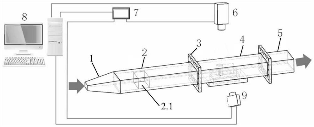
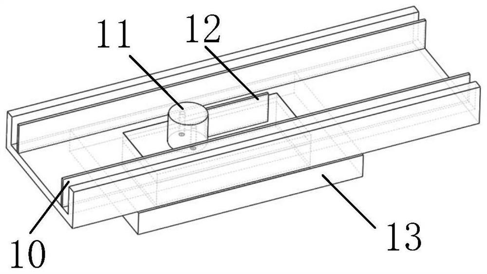
[0026] Refer to attached Figure 1 ~ Figure 4 , an experimental test device for the effect of flow control technology on a flow field under a limited channel condition, comprising a constriction section 1, a rectification section 2, a replaceable test section 4 and a tail section 5 that are sequentially connected and constitute a fluid flow area; the constriction section 1. The structure of expansion and variable diameter is adopted, and the inner diameter increases with the flow direction; the rectification section 2 is equipped with a rectification device 2.1 with a hornet's honeycomb structure; the two ends of the replaceable test section 4 are respectively connected to the rectification section 2 and the tail section 5 through quick-release flanges 3 The upper part of the replaceable test se...


PUM


Abstract

The invention provides an experimental testing device for a flow field effect of a flow control technology under a limited channel condition. The experimental testing device comprises a contraction section, a rectification section, a replaceable testing section and a tail section which are sequentially connected to form a fluid flow area, wherein the contraction section adopts an expansion reducing structure, and the inner diameter of the contraction section is increased along with the flow direction; a rectification device is arranged in the rectification section; two ends of the replaceabletesting section are respectively connected with the rectification section and the tail section through quick release flanges; a CCD (Charge coupled device) camera is arranged at the upper part of thereplaceable testing section and is used for carrying out visual shooting on an experiment; the replaceable testing section comprises adjustable wall surfaces, a bluff body, a partition plate and a quick release plate, the adjustable wall surfaces are arranged at two sides of the bottom in the replaceable testing section, and the width parameter of the replaceable testing section can be changed byadjusting the placing positions of the adjustable wall surfaces; and the bluff body and the partition plate are arranged on the quick release plate and are placed in a flow channel through the detachable connection of the quick release plate and the replaceable testing section. The experimental testing device provided by the invention has the advantages of simplicity in disassembly and maintenance, easiness in adjusting structural parameters, high experimental efficiency, accurate experimental result and the like.

Description

technical field [0001] The invention belongs to a fluid flow test device, in particular to an experimental test device for the effect of flow control technology on a flow field under the condition of limited channels. Background technique [0002] Flow around a bluff body is an important and classic fluid mechanics problem. The flow process involves flow phenomena such as vortex shedding and flow separation. Many flow mechanisms have not been fully understood. Blunt body flow phenomenon occurs in various industries. For example, in the chemical energy field, the bluff body flow phenomenon is used to enhance heat transfer or increase the mass transfer rate. In the measuring instrument industry, the bluff body flow phenomenon is used to measure fluid velocity. In bridge engineering, the bridge vibration problem caused by the flow around the bluff body must be considered. It can be seen that the study of the flow mechanism in the flow around the bluff body has obvious social an...

Claims


Application Information

Patent Timeline
IPC IPC(8): G01M10/00
CPCG01M10/00
Inventor 刘凯史宝成张兴凯伍丽娟廖锐全
Owner YANGTZE UNIVERSITY
Learn More