Hybrid power driving system and vehicle
A drive system, hybrid technology, applied in hybrid vehicles, motor vehicles, power units, etc., can solve the problems of inability to realize parking power generation, poor motor speed regulation function, small output torque, etc., to achieve efficient work, convenient The effect of speed regulation and quantity reduction
- Summary
- Abstract
- Description
- Claims
- Application Information
AI Technical Summary
Problems solved by technology
Method used
Image

Examples
no. 1 example
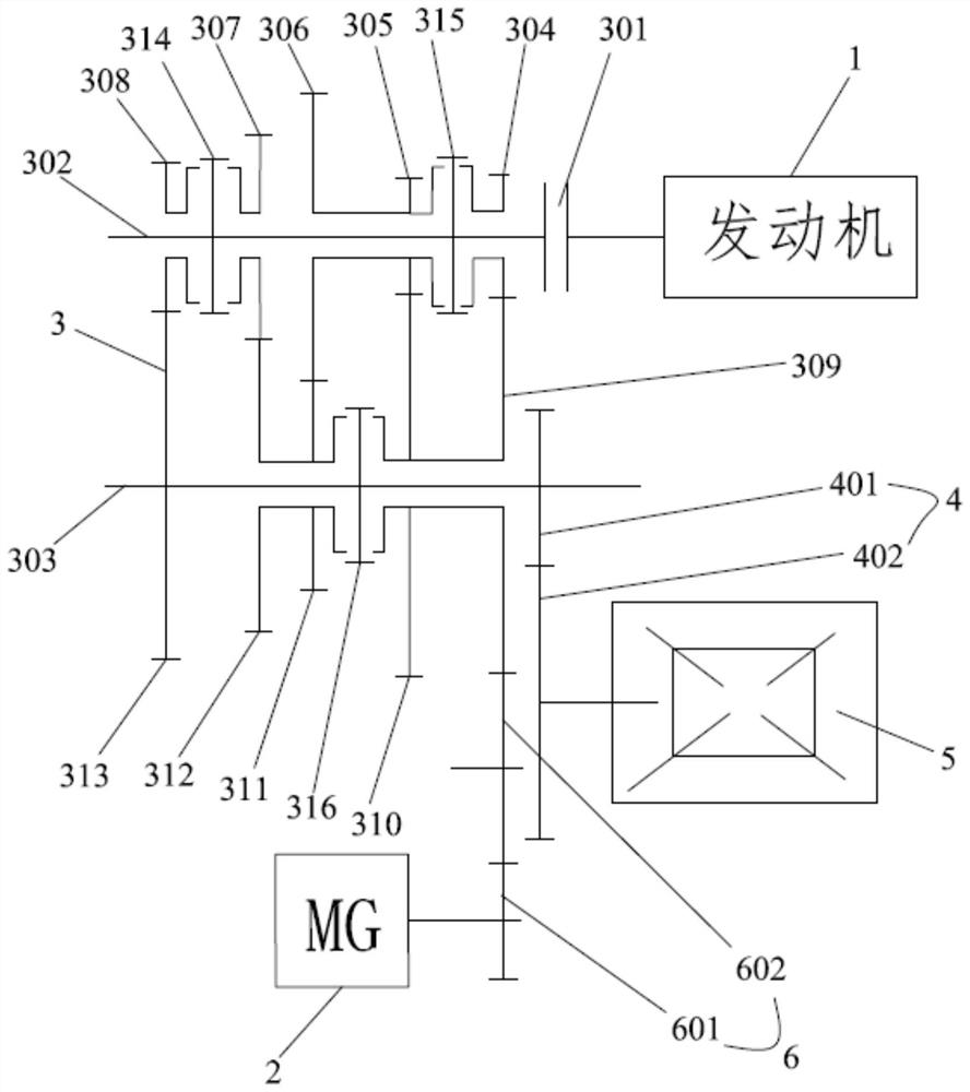
[0066] Such as figure 1 As shown, the hybrid drive system 100 provided in the first embodiment of the present application includes an engine 1 , a gearbox and a motor 2 , and the gearbox includes a speed change mechanism 3 and a final reducer 4 .
[0067] The speed change mechanism 3 includes a clutch device 301, an input shaft 302, an output shaft 303, a synchronizing device, a plurality of driving gears arranged on the input shaft 302 and a plurality of driving gears arranged on the output shaft 303 and a plurality of the driving gears arranged on the output shaft 303. The gears correspond to a plurality of driven gears, and the clutch device 301 is connected between the engine 1 and the input shaft 302 . The motor 2 is connected to the output shaft 303 through a reduction gear set, and the output shaft 303 is connected to the final reducer to output power.
[0068] The final reducer 4 includes a final reducer driving gear 401 and a final reducer driven gear 402 meshing wit...
no. 2 example
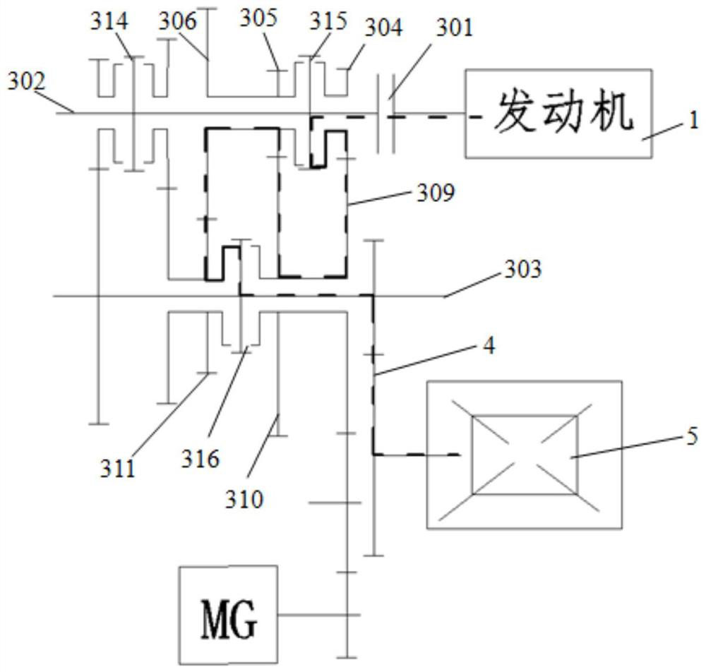
[0100] Figure 21 A hybrid drive system 100 of a second embodiment of the present application is shown.
[0101] In the second embodiment, the plurality of driving gears include a first driving gear 304 , a second driving gear 305 , a third driving gear 306 , The fourth driving gear 307 and the fifth driving gear 308; the plurality of driven gears include a first driven gear 309 and a second driven gear arranged on the output shaft 303 in sequence in a direction away from the engine 1 310, the third driven gear 311, the fourth driven gear 312 and the fifth driven gear 313, the second driven gear 310, the third driven gear 311, the fourth driven gear 312 and the fifth driven gear The gear 313 is idly sleeved on the output shaft 303, and the first driven gear 309 is fixed on the output shaft 303; the first driving gear 304 meshes with the first driven gear 309, and the second driving gear 309 meshes with the first driven gear 309; The gear 305 meshes with the second driven gea...
no. 3 example
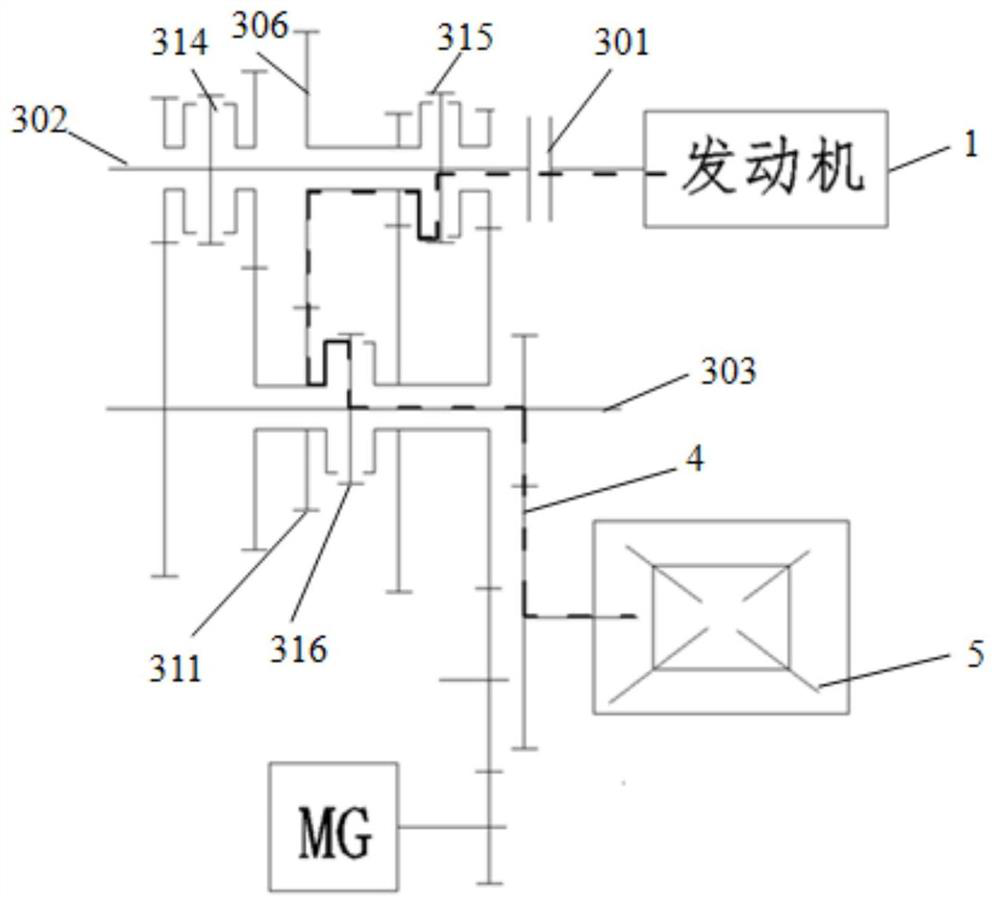
[0105] Figure 22 A hybrid drive system 100 of a third embodiment of the present application is shown.
[0106] In the third embodiment, the plurality of driving gears include a first driving gear 304, a second driving gear 305, a third driving gear 306, a Four driving gears 307 and the fifth driving gear 308, the first driving gear 304, the second driving gear 305, the third driving gear 306 and the fourth driving gear 307 are sleeved on the input shaft 302, and the fifth driving gear The driving gear 308 is fixed on the input shaft 302; the plurality of driven gears include a first driven gear 309, a second driven gear 309, and a second driven gear that are successively sleeved on the output shaft 303 in a direction away from the engine 1. gear 310, the third driven gear 311, the fourth driven gear 312 and the fifth driven gear 313; the first driving gear 304 meshes with the first driven gear 309, and the second driving gear 305 meshes with the second The driven gear 310 m...
PUM
 Abstract
Description
Claims
Application Information
 - R&D
- Intellectual Property
- Life Sciences
- Materials
- Tech Scout
- Unparalleled Data Quality
- Higher Quality Content
- 60% Fewer Hallucinations
Browse by: Latest US Patents, China's latest patents, Technical Efficacy Thesaurus, Application Domain, Technology Topic, Popular Technical Reports.
© 2025 PatSnap. All rights reserved.Legal|Privacy policy|Modern Slavery Act Transparency Statement|Sitemap|About US| Contact US: help@patsnap.com