Supercharge Your Innovation With Domain-Expert AI Agents!

Conical pendulum-applied ball screw type memory inerter device

A ball screw type, inertial memory container technology, applied in the field of inertial container devices, can solve the problems of large damping force, large parasitic damping, constant inertia coefficient, etc., achieve small parasitic damping force, enhance adaptability, structure simple effect

Pending Publication Date: 2020-12-25
JIANGSU UNIV
View PDF9 Cites 0 Cited by
  • Summary
  • Abstract
  • Description
  • Claims
  • Application Information

AI Technical Summary

Problems solved by technology

[0003] International patent PCT / GB02 / 03056 and international patent PCT / GB2010 / 001491 respectively disclose a ball screw type inerter device and a hydraulic inerter device. The hydraulic inerter device utilizes the mass of the oil flowing through the spiral channel to generate inertial force, but the inertia coefficient of these devices is constant and cannot adapt to changes in the working conditions of the mechanical vibration system
[0004] The international patent PCT / CN2016 / 089855 discloses a hydraulic inertial container device, which realizes the adjustment function of the inertial mass, but the device will generate a large parasitic damping during operation, resulting in a damping force greater than the inertial force, affecting the inertial container The actual use effect
[0005] The invention provides a ball screw type memory inertia container device using a conical pendulum. The device replaces the flywheel with a conical pendulum, which overcomes the disadvantage that the inertial coefficient of the inerter is constant

Method used


Image

  • Conical pendulum-applied ball screw type memory inerter device
  • Conical pendulum-applied ball screw type memory inerter device
  • Conical pendulum-applied ball screw type memory inerter device

Examples


Embodiment 1

[0051] After replacing the flywheel with a conical pendulum in Embodiment 1, the inertia coefficient b in formula (2) can be rewritten as:

[0052]

[0053] Then the kinetic equation of the speed-dependent memory inertia container device described in embodiment 1 and 2 can be expressed as:

[0054] p=b(v)v (6)

[0055] The above formula shows that the inertial characteristics of the device described in Embodiments 1 and 2 are related to the relative speeds of the two ends of the device, so it can be seen that the device described in Embodiments 1 and 2 is a speed-dependent type inerter device.

[0056] Taking the main parameters shown in Table 1 as an example, the mechanical properties of the devices described in Examples 1 and 2 will be described below. The main parameters of the device are shown in Table 1, which is taken as the velocity excitation v=Acos(2πft), where the amplitude A is taken as 0.02m, and the frequency f is taken as 1Hz. The force characteristic curve o...

Embodiment 4

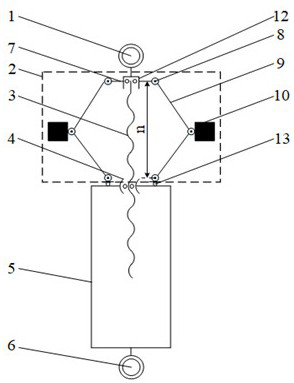
[0063] The main difference between embodiment 4 and embodiment 3 is that in embodiment 3, the screw drives the conical pendulum to rotate, while in embodiment 4, the screw nut drives the conical pendulum to rotate.

[0064] Below to image 3 The shown screw rotating type memory container device is taken as an example to illustrate the technical principles and effects of Embodiments 3 and 4.

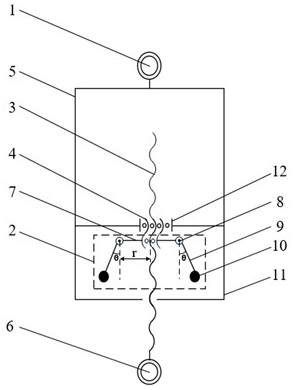
[0065] It can be seen from formula (2) that the inertial coefficient of the ball screw type inerter is related to the moment of inertia I and the lead screw pitch P. Specifically in Embodiment 3, the moment of inertia I of the conical pendulum 2 is related to the displacement of the lead screw, that is, the displacement of both ends of the inerter container, and the relationship between the moment of inertia I and the displacement x can be described by the following formula.

[0066]

[0067] In the formula, x is the displacement of the lead screw, l is the length of the swing arm, m ...


PUM


Abstract

The invention relates to a conical pendulum-applied ball screw type memory inerter device. The conical pendulum-applied ball screw type memory inerter device involves a speed-dependent ball screw typememory inerter device or a displacement-dependent ball screw type memory inerter device, wherein the speed-dependent ball screw type memory inerter device involves a speed-dependent screw rotating ball screw type memory inerter device or a speed-dependent nut rotating ball screw type memory inerter device, and the displacement-dependent ball screw type memory inerter device involves a displacement-dependent screw rotating ball screw type memory inerter device or a displacement-dependent nut rotating ball screw type memory inerter device. According to the conical pendulum-applied ball screw type memory inerter device, a conical pendulum is adopted to replace a traditional flywheel, the force control characteristic that the inertia mass coefficient changes along with the relative speed or the relative displacement is obtained, the ball screw type memory inerter device with the variable inertia mass coefficient is provided, and the defects that the inertia mass of an inerter is not changed and parasitic damping of a hydraulic memory inerter is large are overcome.

Description

technical field [0001] The invention relates to an inerter device, in particular to a ball screw type inerter device using a conical pendulum structure. Background technique [0002] Inerter is a new mechanical component, its concept was put forward in 2002. An inerter has two independently movable endpoints, the relative acceleration of these two endpoints is proportional to the force exerted on the two endpoints, and one endpoint of the mass element is its center of mass, and the other endpoint is the inertial reference frame. A fixed point (mechanical ground), therefore, in the "force-current" correspondence, the mass element can only be compared to a grounded capacitor. Unlike traditional mass elements, an inerter has two independently movable endpoints, which make it unnecessary to be connected to an inertial frame of reference, and therefore, an inerter is similar to an ungrounded capacitor. It can be seen that the correspondence between the inerter, the damper and t...

Claims


Application Information

Patent Timeline
IPC IPC(8): F16F15/14
CPCF16F15/1464F16F15/1478
Inventor 张孝良朱志远聂佳梅陈龙
Owner JIANGSU UNIV
Features
  • R&D
  • Intellectual Property
  • Life Sciences
  • Materials
  • Tech Scout
  • Unparalleled Data Quality
  • Higher Quality Content
  • 60% Fewer Hallucinations
Learn More