Assembly type composite floor

A prefabricated and floor technology, applied in the direction of floors, buildings, building structures, etc., can solve the problems of difficulty in laying the floor at the edge corners, waste of manpower, and floor removal.

Pending Publication Date: 2020-12-25
GOLD MANTIS FINE DECORATION TECH SUZHOU CO LTD
View PDF0 Cites 1 Cited by
  • Summary
  • Abstract
  • Description
  • Claims
  • Application Information

AI Technical Summary

Problems solved by technology

There are many classifications of floors, classified by structure: solid wood floor, laminated wood floor, three-layer parquet, bamboo floor, anti-corrosion floor, cork floor and the most popular multi-layer parquet, etc.; classified by use: Household, commercial use, anti-static floor, outdoor floor, special floor for stage dance, special floor for sports hall, special floor for track and field, etc.; classified by environmental protection level: E0 floor, E1 floor, F4 floor, JAS star Standard F4 star floor, etc., because there will be gaps between the floors after laying, and the gap will expand after long-term use, so there is a prefabricated composite floor. Blocks can be used to connect two floors by snapping them into the inner cavity of the slot to avoid gaps. However, when laying the existing prefabricated combined floor, it needs to be installed from the side, and the blocks are snapped into the inner cavity of the slot. However, due to the limited indoor operating space, it is very difficult to lay the floor at the edge of the corner. At the same time, after a single floor is damaged, it needs to be removed in a large area, otherwise the damaged floor cannot be removed, resulting in a waste of manpower and material resources. Therefore, we propose a prefabricated composite floor

Method used


Image

  • Assembly type composite floor
  • Assembly type composite floor
  • Assembly type composite floor

Examples


Embodiment 1

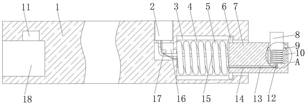
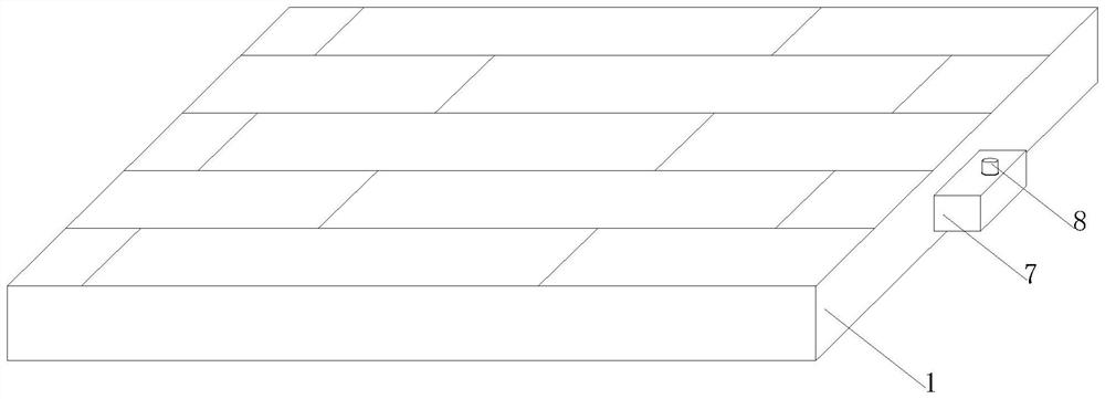
[0022] An assembled combined floor, comprising a floor 1, one side of the floor 1 is provided with a fixing groove 18, the interior of the floor 1 is provided with a limit card groove 11 at the top of the cavity of the fixing groove 18, and the other end of the floor 1 is provided with a second A chute 4, the inside of the floor 1 is provided with first limiting grooves 3 located on the upper and lower sides of the first chute 4, the inside of the floor 1 is provided with a socket hole 16, and the socket hole 16 is connected to the first chute 4 Through, the inner cavity of the first chute 4 is movably socketed with a sleeve column 7, and one end of the sleeve column 7 is fixedly installed with a first support spring 5 located in the inner cavity of the first chute 4, and one end of the first support spring 5 Fixedly connected to one end of the inner cavity of the first chute 4, the surface of one end of the sleeve post 7 is fixedly connected to the first limit post 6, the numb...

Embodiment 2

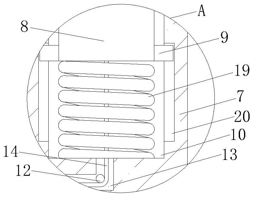
[0024] The middle part of one end of the socket column 7 is fixedly connected with a second backguy 15, and one end of the second backguy 15 extends to the inner cavity of the socket hole 16 and is fixedly connected with a pull plug 2, and the center of the bottom of the limit block 8 is fixedly connected with a second backguy. A pull wire 14, one end of the first pull wire 14 runs through the inner cavity of the cable arrangement groove 13 and the first chute 4 and extends to the inner cavity of the sleeve hole 16, and one end of the first pull wire 14 is fixedly connected to the bottom of the pull plug 2, The pull plug 2 is movably socketed to the inner cavity of the sleeve hole 16, and the inner cavity of the sleeve hole 16 is fixedly connected with a second rotating column 17, and the second rotating column 17 is located above the second pull wire 15 and the first pull wire 14, The length of the second backguy 15 located in the inner cavity of the sleeve hole 16 is greater ...


PUM


Abstract

The invention discloses an assembly type composite floor, and relates to the technical field of floors. The assembly type composite floor comprises a floor body, a fixing groove is formed in one sideof the floor body, a limiting clamping groove located in the top of an inner cavity of the fixing groove is formed in the floor body, a first sliding groove is formed in the other end of the floor body, first limiting grooves located in the upper side and the lower side of the first sliding groove are formed in the floor body, and a sleeving hole is formed in the floor body. According to the assembly type composite floor, a first supporting spring, a sleeving column, a limiting clamping block, a pushing spring, the fixing groove and the limiting clamping groove are matched for use, the sleeving column is supported by the first supporting spring, the limiting clamping block is supported by the pushing spring, and during assembling, the sleeving column and the limiting clamping block are connected to the inner cavity of the fixing groove and the inner cavity of the limiting clamping groove in a sleeved mode respectively, then two floor bodies can be assembled, and a gap can be effectively prevented from being generated between the two floor bodies.

Description

technical field [0001] The invention relates to the field of floor technology, in particular to an assembled composite floor. Background technique [0002] Floor, that is, the surface layer of the ground or floor of a building. Made of wood or other materials. There are many classifications of floors, classified by structure: solid wood floor, reinforced composite wood floor, three-layer solid wood composite floor, bamboo wood floor, anti-corrosion floor, cork floor and the most popular multi-layer solid wood composite floor, etc.; classified by use: Household, commercial use, anti-static floor, outdoor floor, special floor for stage dance, special floor for sports hall, special floor for track and field, etc.; classified by environmental protection level: E0 floor, E1 floor, F4 floor, JAS star Standard F4 star floor, etc., because there will be gaps between the floors after laying, and the gap will expand after long-term use, so there is a prefabricated composite floor. ...

Claims


Application Information

Patent Timeline
IPC IPC(8): E04F15/02E04F15/04
CPCE04F15/02E04F15/02038E04F15/04E04F2201/021E04F2201/05
Inventor 王举光施再元孟春海戚叶
Owner GOLD MANTIS FINE DECORATION TECH SUZHOU CO LTD
Why Eureka
Try Eureka