
Rapid pavement marking device for highway construction

A marking device and fast technology, applied in the direction of roads, roads, road repair, etc., can solve the problems that the new marking lines are not consistent with the old marking lines, affect the aesthetics of the marking lines, and have low work efficiency, so as to improve the warning ability. , The effect of high scribing efficiency and low cost

Pending Publication Date: 2020-12-25
潘龙
View PDF0 Cites 3 Cited by
  • Summary
  • Abstract
  • Description
  • Claims
  • Application Information

AI Technical Summary

Problems solved by technology

[0003] In the process of road construction or maintenance, new markings are drawn on the road surface, and new markings are drawn on the basis of the original old markings. When the old markings are renovated, the direction of the marking device must be consistent with the old ones The marking lines are consistent, and if there is a deviation, it will affect the aesthetics of the marking lines. When the existing marking devices are renovating the old marking lines, most of them use artificial corrections and use eyes to correct them, so that the marking devices are consistent with the old markings. However, this operation is not only time-consuming and labor-intensive, but also prone to deviations, which makes the new marking line inconsistent with the old marking line, and the work efficiency is low

Method used


Image

  • Rapid pavement marking device for highway construction
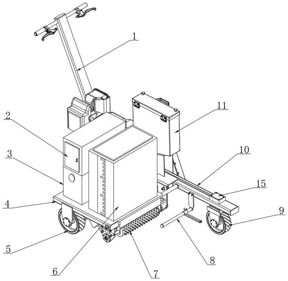
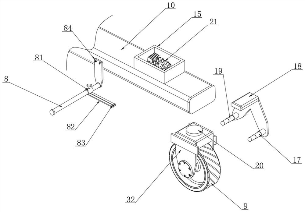
  • Rapid pavement marking device for highway construction
  • Rapid pavement marking device for highway construction

Examples


Embodiment Construction

[0021] The technical solutions in the embodiments of the present invention will be clearly and completely described below with reference to the accompanying drawings in the embodiments of the present invention. Obviously, the described embodiments are only a part of the embodiments of the present invention, but not all of the embodiments. Based on the embodiments of the present invention, all other embodiments obtained by those of ordinary skill in the art without creative efforts shall fall within the protection scope of the present invention.

[0022] see Figures 1 to 6 , in the embodiment of the present invention, a road surface rapid marking device for highway construction, including a push rod 1, the lower end of the push rod 1 is connected with a main strut 10, one side of the main strut 10 is connected with a base 4, the base The upper end of 4 is provided with a storage box 3 and a material box 6 side by side, the storage box 3 is stored with reflective microbeads, th...


PUM


Abstract

The invention discloses a rapid pavement marking device for highway construction, and relates to the technical field of highway construction. The rapid pavement marking device comprises a push rod, wherein a main supporting rod is connected to the lower end of the push rod, and a base is connected to one side face of the main supporting rod; driving wheels are arranged on the rear side of the lower end of the base, and a cleaning roller is connected to the front side of the lower end of the base; and a guide wheel is arranged on the lower surface of the front end of the main supporting rod, apositioning rod is connected to the position, located behind the guide wheel, of one side face of the main supporting rod, a connecting rod is arranged at the position, corresponding to the guide wheel, of the outer side face of the front end of the main supporting rod, and a first push rod and a second push rod are arranged at the positions, corresponding to the front and rear ends of the guide wheel, of the inner side of the connecting rod side by side. According to the rapid pavement marking device for highway construction, it can be ensures that the inner side edge of the guide wheel always corresponds to the outer side edge of an old marking line, so that the problem that a drawn marking line is not accurate enough due to deviation of a marking device during marking is solved, meanwhile, the problem that traditional manual correction is not accurate enough is also solved, and time and labor are saved; and intelligent calibration is achieved, so that the rapid pavement marking device is more accurate and high in marking efficiency.

Description

technical field [0001] The invention relates to the technical field of highway construction, in particular to a road surface rapid marking device for highway construction. Background technique [0002] Road marking is an important technical measure to guide traffic signs and ensure traffic safety, and is an essential part of road engineering construction. Road marking requires a marking device to implement, and road marking can be divided into hot melt marking, room temperature cold paint marking, color non-slip marking, oscillating non-slip reflective marking and pre-forming marking, which refers to the marking on the road. Lines, arrows, text, elevation marks, raised road signs and outline signs are used on the road surface to convey traffic information such as guidance, restrictions, and warnings to traffic participants. Its function is to control and guide traffic. It can be used in conjunction with signs or alone. In order to make road markings clearer, microbead spray...

Claims


Application Information

Patent Timeline
Patent Type & Authority Applications(China)
IPC IPC(8): E01C23/20
CPCE01C23/20E01C23/206
Inventor 单宝华胡涛潘龙
Owner 潘龙
Learn More