
Production equipment with rotating function for automobile plastic part welding

A technology of rotating function and production equipment, which is applied in household appliances, other household appliances, applications, etc., can solve the problems of inaccurate welding position, inability to close the reverse side panel, inconvenient welding operation, etc., and achieve the effect of easy clamping

Inactive Publication Date: 2020-12-25
东莞市达盛机电设计有限公司
View PDF0 Cites 2 Cited by
  • Summary
  • Abstract
  • Description
  • Claims
  • Application Information

AI Technical Summary

Problems solved by technology

[0004] The purpose of the present invention is to provide a kind of production equipment with rotating function for welding plastic parts of automobiles, so as to solve the problem of installing a fixed hook on the outer panel and installing an elastic rope on the outer panel, so as to facilitate hanging by the elastic rope when unscrewing the fuel tank cap. On the panel, it is usually hand-welded by the master, and because the hook part is relatively small, the hook part is usually fixed with a clamp when the master is operating, so the welding operation is not very convenient, and it is more likely to be caused by inaccurate welding positions. Backfired, the outer panel could not be closed, etc.

Method used


Image

  • Production equipment with rotating function for automobile plastic part welding
  • Production equipment with rotating function for automobile plastic part welding
  • Production equipment with rotating function for automobile plastic part welding

Examples


Embodiment Construction

[0026] The technical solutions in the embodiments of the present invention will be clearly and completely described below in conjunction with the accompanying drawings in the embodiments of the present invention. Obviously, the described embodiments are only some of the embodiments of the present invention, not all of them. Based on The embodiments of the present invention and all other embodiments obtained by persons of ordinary skill in the art without making creative efforts belong to the protection scope of the present invention.

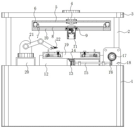
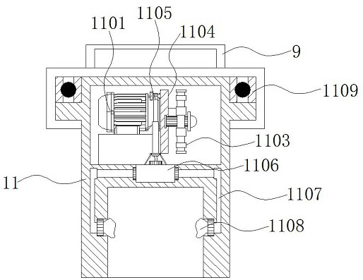
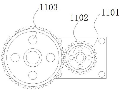
[0027] see Figure 1-5 , the present invention provides a technical solution: a production equipment with rotating function for welding plastic parts of automobiles, comprising a bottom chassis 1, the upper surface of the bottom chassis 1 is symmetrically provided with a support frame 2, and the top of the support frame 2 is arranged on the top plate 3 inside the four corners, the bottom surface of the top plate 3 is equipped with a rotating col...


PUM


Abstract

The invention discloses production equipment with a rotating function for automobile plastic part welding. The production equipment comprises a bottom machine box, wherein supporting frames are symmetrically arranged on the upper surface of the bottom machine box, and the tops of the supporting frames are arranged inside the four corners of a top plate; a workbench is arranged on the surface of the upper portion of the bottom machine box, a driven shaft is arranged in the middle of the interior of the workbench, and a second driven gear is arranged above the driven shaft; and a base is arranged at the position, on the left side of the workbench, of the surface of the bottom machine box, a mechanical arm is connected to the upper portion of the base, and a laser welding head is arranged inside the right side of the mechanical arm. According to the production equipment with a rotating function for automobile plastic part welding, a clamping mechanism and a fixing mechanism are arranged above the workbench, and through the arrangement of the fixing mechanism, a face plate can be conveniently fixed in position, so that position movement during welding is avoided; and meanwhile, throughthe arrangement of the clamping mechanism, a hook can be conveniently clamped, so that an external tool is avoided from being used for clamping the hook, and then the stability of the welding face ofthe face plate and the hook is facilitated.

Description

technical field [0001] The invention relates to the technical field of automobile welding, in particular to a production equipment with rotating function for welding automobile plastic parts. Background technique [0002] Automobile body components are mainly made of cold-rolled steel stamping parts with good stamping and welding process, which are assembled and welded. The welding production batch is large, the production speed is fast, and the assembly and welding accuracy of the welded parts is high, and the assembly and welding precision of the welded parts is mostly used. The production method is mechanized and highly automated. A large number of special equipment and fixtures are used. More and more welding work is done by automatic welding machines and welding robots. The resistance heat generated when the current passes through the workpiece is used to heat the workpiece for welding. Welding includes: spot welding, seam welding, projection welding, butt welding. [...

Claims


Application Information

Patent Timeline
IPC IPC(8): B29C65/16B29C65/78B29L31/30
CPCB29C65/16B29C65/7841B29C66/80B29L2031/30
Inventor 李颖琼刘增铭梁聪
Owner 东莞市达盛机电设计有限公司
Learn More