Machining process and die for injection piston body

A technology of injection piston and processing technology, applied in the field of mechanical forging, can solve the problems of high production cost and poor stability, achieve the effect of high precision and avoid assembly errors

Pending Publication Date: 2020-12-25
HAITIAN PLASTICS MACHINERY GRP
View PDF7 Cites 0 Cited by
  • Summary
  • Abstract
  • Description
  • Claims
  • Application Information

AI Technical Summary

Problems solved by technology

[0005] Aiming at the disadvantages of high production cost and poor stability after assembly in the prior art that the piston and piston rod are separately processed and assembled, the inventio...

Method used


Image

  • Machining process and die for injection piston body

Examples


Embodiment

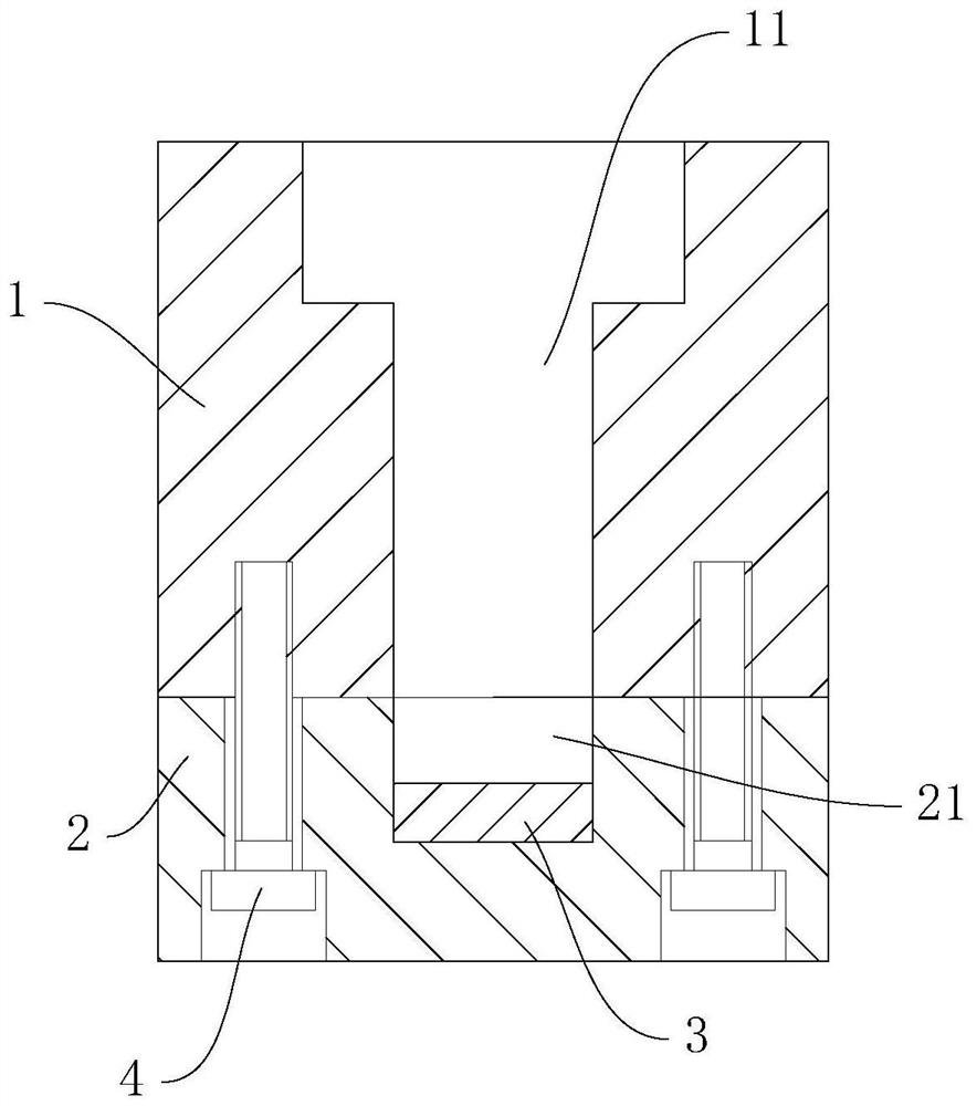
[0028] A kind of mold of injection piston body, see attached figure 1 , including an upper mold body 1 and a lower mold body 2, the upper mold body 1 has a basic cavity 11 for forming a basic piston body, and the lower mold body 2 is provided with a variable cavity 21 for extending the length of the piston rod, wherein the change is set in the variable type The thickness of the insert 3 in the cavity 21 can realize changing the length of the piston rod to be forged. The upper mold body 1 and the lower mold body 2 are fixed by bolts 4 .

[0029] When forging, the extrusion force of the basic cavity 11 is relatively large, so that the deformation of the basic cavity 11 is relatively large, but since the basic cavity 11 and the variable cavity 21 are arranged separately, and the variable cavity 21 is located below, When forging, the extrusion force that the variable cavity 21 bears is very small, and the variable cavity 21 hardly produces expansion deformation, and then there is...


PUM


Abstract

The invention relates to the field of mechanical forging, and discloses a machining process and die for an injection piston body. The machining process comprises the following steps of a, material preparing; b, heating; c, die forging; d, rough machining; e, subsequent heat treatment; and f, finish machining. A piston and a piston rod are integrally forged as a whole and then are machined, the brand-new machining mode can avoid the problem that the machining cost is too high due to losses of a base material, and therefore, the economical efficiency is improved, fit clearances caused by independent turning machining can be completely eliminated, and the overall stability performance is improved.

Description

technical field [0001] The invention relates to the field of mechanical forging, in particular to a processing technology and mold for an injection piston body. Background technique [0002] The injection piston body is the abbreviation of the integrated hydraulic connection part of the piston and the piston rod. Through the pressure transmission of the hydraulic oil, it drives the forward and backward movements of the injection screw. It is a part with frequent movements and high technical requirements. [0003] The general processing method in the existing industry is: turning the piston and the piston rod as separate entities, and then assembling after the processing is completed. Its main disadvantage is that the existing piston rod blank is directly cast with the whole round steel, so it takes a lot of time to turn from the blank size to the small end outer diameter size turning. In the process, there is a lot of waste of cutting tools and raw materials, which leads to...

Claims


Application Information

Patent Timeline
IPC IPC(8): B23P15/10
CPCB23P15/10
Inventor 俞健勇张永福谢学兴
Owner HAITIAN PLASTICS MACHINERY GRP
Why Eureka
Try Eureka