Fully automatic welding device for box type room
A fully automatic welding and automatic welding technology, which is applied in welding equipment, auxiliary equipment, auxiliary welding equipment, etc., can solve the problems of low profile efficiency and achieve the effects of improving efficiency, fast unloading, and improving feeding efficiency
- Summary
- Abstract
- Description
- Claims
- Application Information
AI Technical Summary
Problems solved by technology
Method used
Image
Examples
Embodiment 1
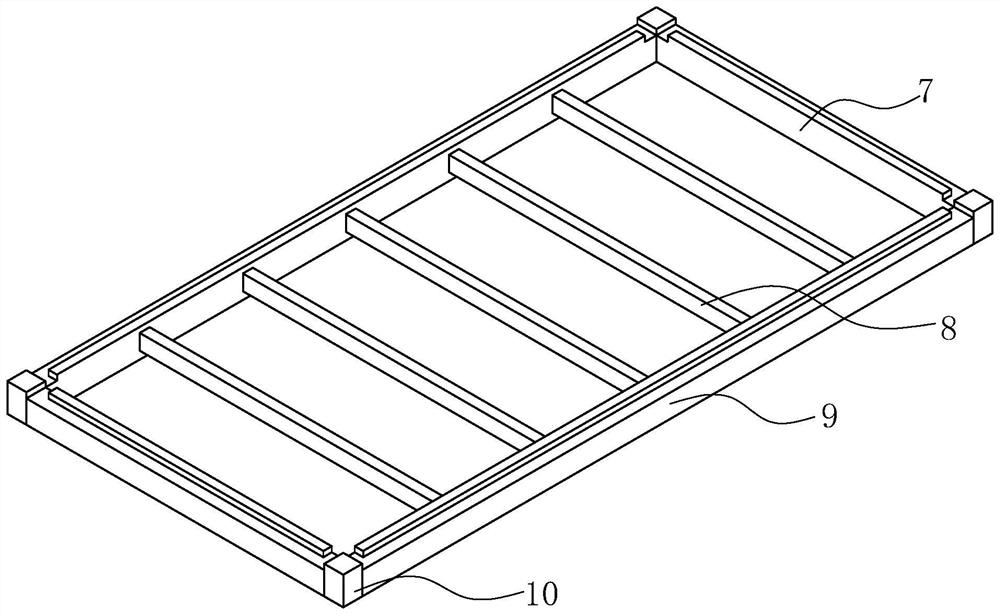
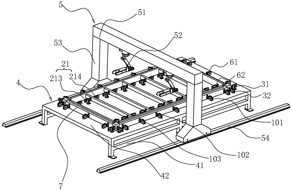
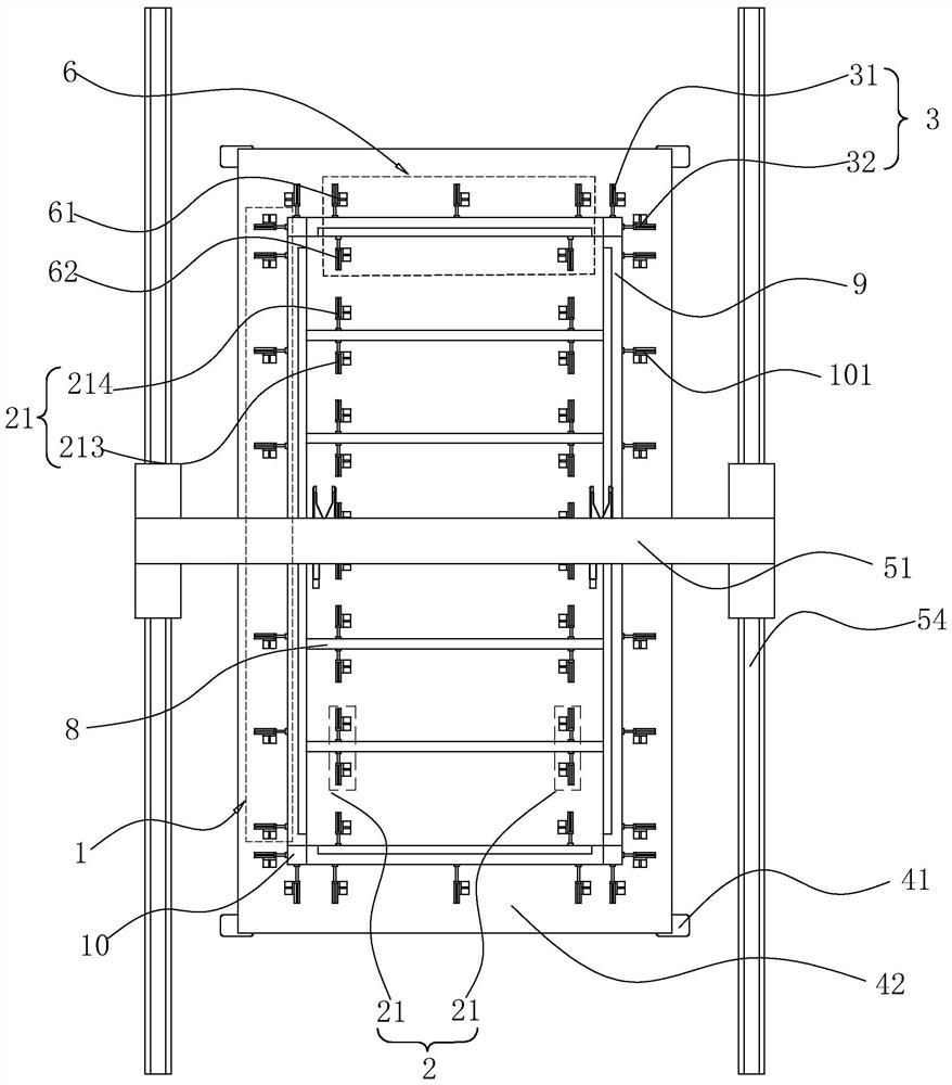
[0049] refer to figure 2 and image 3 , The fully automatic welding device for box-type houses disclosed in this embodiment includes a welding workbench 4 and an automatic welding device 5, and the welding workbench 4 is used to fix the longitudinal profile 9 and the transverse profile. The automatic welding device 5 adopts a gantry welding device, including a gantry frame and a guide rail 54, and the gantry frame includes a crossbeam 51 and columns 53 arranged at the two ends of the crossbeam 51. Upright column 53 is arranged on the both sides of welding workbench 4, and the bottom of upright column 53 is connected with guide rail 54, and guide rail 54 is distributed in the both sides of welding workbench 4, and distributes along the length direction of welding workbench 4, and gantry can be on the guide rail 54 on the move. Two welding manipulators 52 are arranged on the beam 51 for welding the fixed longitudinal profile 9 and the transverse profile fixed on the welding t...
Embodiment 2
[0061] All the rest in this embodiment are the same as in Embodiment 1. The difference is that this embodiment adds an automatic feeding mechanism 11 for a horizontal profile. Since the length of the entire workbench 42 is long and the weight of the horizontal profile is not light, It is very labor-intensive to manually discharge the horizontal profiles one by one and place them in the designated position. Therefore, in this embodiment, a horizontal profile automatic feeding mechanism 11 is added to realize the discharging of the horizontal profiles, reducing the The workload of the operator.
[0062] refer to Figure 5 and Figure 6 , In this embodiment, a horizontal profile automatic feeding mechanism 11 is also provided on the workbench 42, and the horizontal profile automatic feeding mechanism 11 includes a belt transmission mechanism. Two belt storage grooves 12 are arranged on the workbench 42, and the belt storage grooves 12 are distributed along the longitudinal direct...
Embodiment 3
[0076] The rest of this embodiment is the same as that of Embodiment 2. The difference is that in order to improve the convenience of feeding the longitudinal profile 9, several groups of guide wheel mechanisms 17 are provided on the workbench 62 for assisting the vertical profile 9. material.
[0077] refer to Figure 9 and Figure 10 , on the workbench 62 is provided with a number of guide wheel mechanism installation grooves 18, the number of guide wheel mechanism installation grooves 18 is determined according to the length of the longitudinal profile 9, generally every 0.4-0.7m along the length direction of the longitudinal profile 9 set one up. The guide wheel mechanism 17 is arranged in the guide wheel mechanism installation groove 18 . Guide wheel mechanism 17 comprises guide wheel 1701, guide wheel base plate 1704, guide wheel lift cylinder 1703, guide wheel 1701 is located at the upper end of guide wheel base plate 1704, the piston rod of guide wheel lift cylinder...
PUM
 Abstract
Description
Claims
Application Information
 - R&D
- Intellectual Property
- Life Sciences
- Materials
- Tech Scout
- Unparalleled Data Quality
- Higher Quality Content
- 60% Fewer Hallucinations
Browse by: Latest US Patents, China's latest patents, Technical Efficacy Thesaurus, Application Domain, Technology Topic, Popular Technical Reports.
© 2025 PatSnap. All rights reserved.Legal|Privacy policy|Modern Slavery Act Transparency Statement|Sitemap|About US| Contact US: help@patsnap.com


