
Suspension type optical transceiver communication device

A technology for communication equipment and optical transceivers, applied in communication-related fields, can solve the problems of reducing the use efficiency of the device, not having the lifting adjustment function, and unable to adjust the device, so as to improve the use efficiency, avoid excessive internal temperature, and avoid misoperation. Effect

Inactive Publication Date: 2020-12-22
广州创利宝科技有限公司
View PDF4 Cites 1 Cited by
  • Summary
  • Abstract
  • Description
  • Claims
  • Application Information

AI Technical Summary

Problems solved by technology

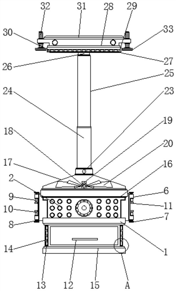
[0004] Aiming at the deficiencies of the prior art, the present invention provides a suspended optical transceiver communication device, which solves the problem that the original suspended optical transceiver communication equipment does not have the function of lifting and lowering during use, and cannot move the device up and down during work. Adjustment handles on both sides, which reduces efficacy issues with the use of the device

Method used


Image

  • Suspension type optical transceiver communication device
  • Suspension type optical transceiver communication device
  • Suspension type optical transceiver communication device

Examples


Embodiment

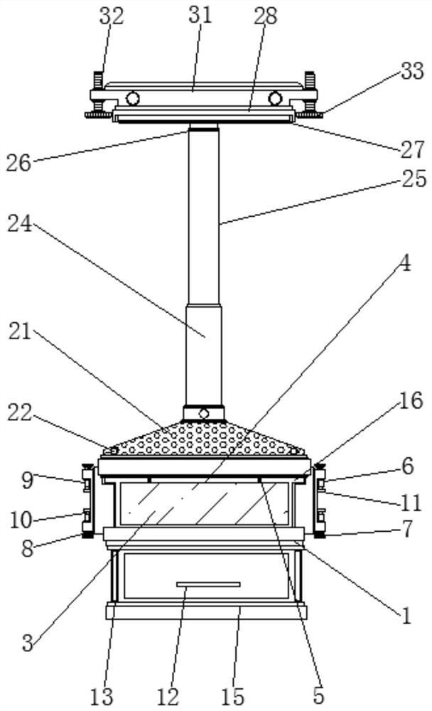
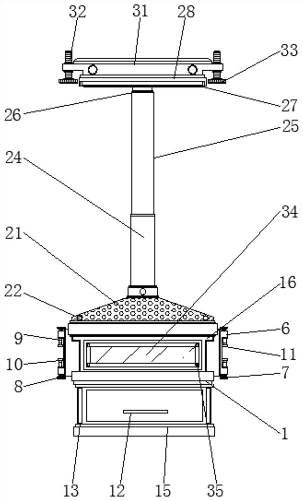
[0038] see Figure 1-6 , in this embodiment: a suspension type optical transceiver communication device, including an optical transceiver 1, a card slot 6, a storage drawer 12, a fixed frame 16, a rotating disk 23 and an inspection port 34, the front surface of the optical transceiver 1 is provided with a control panel 2, and A protective cover 3 is provided on the front surface of the control panel 2, a rotating rod 4 is arranged above the protective cover 3, and rotating bolts 5 are arranged on both sides of the rotating rod 4, and the card slots 6 are arranged on both sides of the outer wall of the optical transceiver 1, and the card slots 6 Both sides are provided with rotating blocks 7, and the inside of the rotating block 7 is provided with a limit rod 8, and the inside of the limit rod 8 is provided with a telescopic sleeve 9, the inside of the telescopic sleeve 9 is provided with a telescopic rod 10, and the inside of the telescopic rod 10 is provided with a fixed groov...


PUM


Abstract

The invention belongs to the technical field of communication, and particularly relates to suspension type optical transceiver communication equipment which comprises an optical transceiver, a clamping groove, a storage drawer, a fixing frame, a rotating disc and an access hole, a control panel is arranged on the front surface of the optical transceiver, a protective cover is arranged on the frontsurface of the control panel, and a rotating rod is arranged above the protective cover. The two sides of the rotating rod are provided with rotating bolts, the clamping grooves are formed in the twosides of the outer wall of the optical transceiver, the two sides of each clamping groove are provided with rotating blocks, limiting rods are arranged on the inner sides of the rotating blocks, telescopic sleeves are arranged on the inner sides of the limiting rods, telescopic rods are arranged on the inner sides of the telescopic sleeves, and fixing grooves are formed in the inner sides of thetelescopic rods. By arranging the protective cover, the control panel can be effectively protected, in the using process, the control panel can be protected according to the using requirement, misoperation caused by collision with the outside is avoided, and therefore the using effect of the device is effectively improved.

Description

technical field [0001] The invention relates to the field of communication-related technologies, in particular to a suspended optical transceiver communication device. Background technique [0002] Communication refers to the exchange and transmission of information between people or between people and nature through a certain behavior or medium. In a broad sense, it refers to the use of any method or medium by two or more parties who need information without violating their respective wishes. Accurately and safely transmit information from one party to another. Communication is the exchange and transmission of information between people through a certain medium. The network is composed of physical links that connect individual workstations or hosts together. Data link, communication network refers to the physical connection of various isolated devices to realize the link of information exchange between people, people and computers, computers and computers, so as to achieve ...

Claims


Application Information

Patent Timeline
Patent Type & Authority Applications(China)
IPC IPC(8): H04B10/40F16M11/04F16M11/18F16M13/02
CPCF16M11/046F16M11/18F16M13/02H04B10/40
Inventor 邓国容
Owner 广州创利宝科技有限公司
Learn More