
Combined relay based on double-miniature PCB relay

A relay and combined technology, applied in the direction of relays, electromagnetic relays, detailed information of electromagnetic relays, etc., can solve the problems of high production cost, limited PCB installation space, cumbersome production process, etc., to ensure a safe distance, reduce production costs, The effect of simplifying the manufacturing process

Pending Publication Date: 2020-12-22
XIAMEN HONGFA AUTOMOTIVE ELECTRONICS
View PDF0 Cites 0 Cited by
  • Summary
  • Abstract
  • Description
  • Claims
  • Application Information

AI Technical Summary

Problems solved by technology

With the continuous expansion of the application field of PCB relays, the application scenario of a PCB relay in the prior art requires the use of two PCB relays. Due to the limited installation space of the PCB board, two separate PCB relays are installed on the PCB board. It will take up a large space. Therefore, in the prior art, two PCB relays are assembled together to form a combined relay. This relay in the prior art is to ensure that the contact between the static spring pins of the two relays and the moving spring The safe distance between the lead-out pins requires careful design of the layout of the lead-out pins of the two relays, that is to say, two sets of molds are needed to make the two relays, resulting in the disadvantages of cumbersome manufacturing process and high manufacturing cost
In addition, in order to achieve the limit of the two relays, the existing technology is to thicken the shell and set the limit by setting retaining walls or ribs, etc., resulting in the disadvantages of complex structure of the shell and increased product volume, which is not conducive to product safety. miniaturization

Method used


Image

  • Combined relay based on double-miniature PCB relay
  • Combined relay based on double-miniature PCB relay
  • Combined relay based on double-miniature PCB relay

Examples


Embodiment

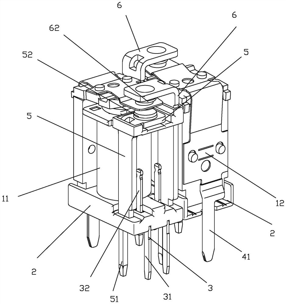
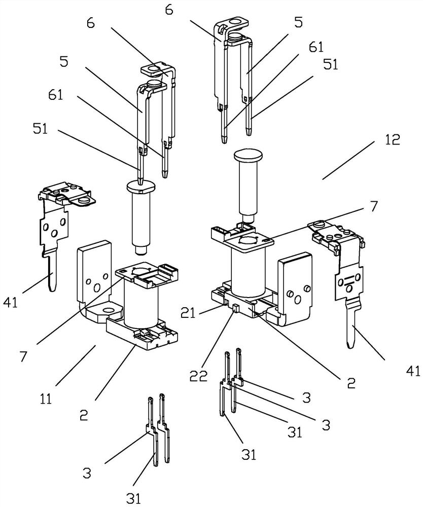
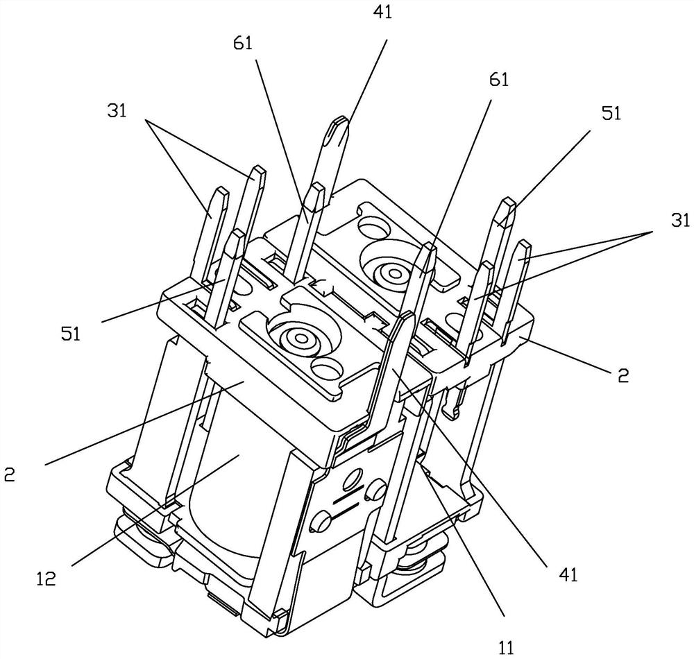
[0039] see Figure 1 to Figure 17 As shown, a combined relay based on dual small PCB relays of the present invention includes two relays 11 and 12 with the same structure and without a housing; the relay includes a base 2 and coil pins 31 distributed on the base , moving spring lead-out pin 41 and static spring lead-out pin, wherein, the quantity of coil lead-out pin 31 is two, static spring lead-out pin has normally open static spring lead-out pin 51 and normally closed static spring lead-out pin 61; Described base 2 is in The projection on the bottom plane has a rectangular shape; the coil lead-out pin 31 and the static spring lead-out pin 51, 61 are arranged at one end of the length of the base 2, and the moving spring lead-out foot 41 is arranged at the other end of the length of the base 2; One side of the lengthwise direction of the base 2 is respectively provided with a groove 21 and a bump 22 at equidistant positions corresponding to both sides of the median line of th...


PUM


Abstract

The invention discloses a combined relay based on a double-miniature PCB relay. The combined relay comprises two relays which are the same in structure and do not comprise shells. Each relay comprisesa base, and a coil lead-out pin, a movable spring lead-out pin and a static spring lead-out pin which are distributed on the base; a groove and a protruding block are arranged on one side edge of thebase in the length direction at equal intervals and located on the two sides of a median line corresponding to the length of the base respectively, when two relays are spliced, one relay is rotated by 180 degrees and then is paired with the other relay, and the grooves and the protruding blocks of the two relays are matched in an oppositely-inserted mode respectively. According to the invention,the safe distance between the static spring lead-out pins and the safe distance between the movable spring lead-out pins of the two relays can be effectively ensured by adopting one mold, so that thepurposes of simplifying the manufacturing process and reducing the manufacturing cost are achieved; and a complex limiting structure does not need to be arranged on the shell, so that the structure ofthe shell is simplified, and the miniaturization of the product is realized.

Description

technical field [0001] The invention relates to the technical field of relays, in particular to a combined relay based on double small PCB relays. Background technique [0002] A PCB relay is a relay for mounting on a PCB (ie, a printed circuit board). Due to the limited mounting space on the PCB, the volume of the PCB relay is usually designed to be small. With the continuous expansion of the application field of PCB relays, the application scenario of a PCB relay in the prior art requires the use of two PCB relays. Due to the limited installation space of the PCB board, two separate PCB relays are installed on the PCB board. It will take up a large space. Therefore, in the prior art, two PCB relays are assembled together to form a combined relay. This relay in the prior art is to ensure that the contact between the static spring pins of the two relays and the moving spring The safe distance between the lead-out pins requires careful design of the layout of the lead-out pi...

Claims


Application Information

Patent Timeline
Patent Type & Authority Applications(China)
IPC IPC(8): H01H50/14H01H50/04H01H50/44H01H50/56
CPCH01H50/04H01H50/043H01H50/14H01H50/443H01H50/56H01H2050/446
Inventor 吴锦书陈红波张方方
Owner XIAMEN HONGFA AUTOMOTIVE ELECTRONICS
Learn More