Camera calibration device

A camera and image correction technology, applied in the field of image correction, can solve the problems of low image correction efficiency and difficulty in mass production, and achieve the effect of simple structure and improved work efficiency

Pending Publication Date: 2020-12-22
SHANGHAI JUYOU SMART INTELLIGENCE TECH CO LTD
View PDF0 Cites 0 Cited by
  • Summary
  • Abstract
  • Description
  • Claims
  • Application Information

AI Technical Summary

Problems solved by technology

[0004] Embodiments of the present disclosure provide a device for camera calibration to at least solve the problem that the current calibration scheme in the prior art is mainly limited by a movable high-precision slide table, and it is difficult to complete multiple non- The correction of ideal parameters requires different correction equipment for different non-ideal parameters, resulting in low efficiency of image correction and technical problems that make it difficult to achieve the purpose of mass production

Method used


Image

  • Camera calibration device
  • Camera calibration device
  • Camera calibration device

Examples


Embodiment

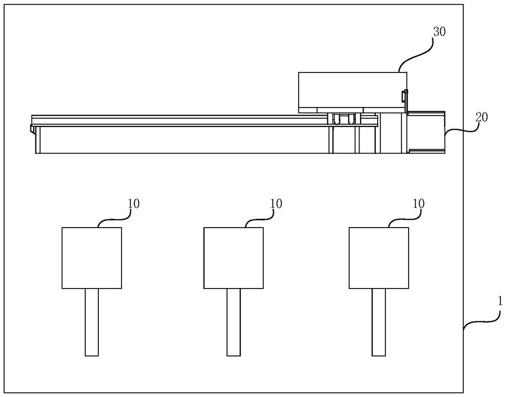
[0023] figure 1 A schematic diagram of the camera calibration device 1 described in this embodiment is shown, refer to figure 1 As shown, the device 1 for camera calibration includes: a plurality of image correction targets 10, a first moving mechanism 20, and a first camera fixing mechanism 30; arrangement, and the target surface of the image correction target 10 is provided with a pattern for correcting the camera; the first camera fixing mechanism 30 is arranged on the first moving mechanism 20, and can move relative to a plurality of image correction targets 10; and a plurality of images A target surface of the calibration target 10 is arranged in the direction of the first movement mechanism 20 .

[0024] Specifically, as figure 1 As shown, the patterns on the target surfaces of multiple image correction targets 10 are, for example but not limited to, carefully designed patterns for wide-angle correction, carefully designed patterns for distortion correction, and carefu...


PUM


Abstract

Disclosed is a camera calibration device (1). The camera calibration device (1) comprises a plurality of image correction targets (10), a first moving mechanism (20) and a first camera fixing mechanism (30). The plurality of image correction targets (10) is arranged along the moving track of the first moving mechanism (20), and the target surface of each image correction target (10) is provided with a pattern for correcting a camera; the first camera fixing mechanism (30) is arranged on the first moving mechanism (20) and can move relative to the plurality of image correction targets (10); andone target surface of the plurality of image correction targets (10) is arranged towards the direction of the first moving mechanism (20).

Description

technical field [0001] The present application relates to the field of image correction, in particular to a device for camera correction. Background technique [0002] There are various non-ideal factors in the current camera modules, such as lens distortion, assembly error, sensitivity correction, stray light interference and so on. Therefore, corresponding calibration equipment is required to perform calibration processing. However, in the current depth camera, there are more non-ideal parameters that need to be corrected, such as distance drift, non-ideal type of distance, and non-ideal type of driving circuit. The current calibration scheme is mainly limited by the movable high-precision sliding table. It is difficult to complete the calibration of multiple non-ideal parameters based on a set of calibration equipment. For different non-ideal parameters, different calibration equipment is required for calibration, resulting in image correction. The efficiency is low, an...

Claims


Application Information

Patent Timeline
Patent Type & Authority Applications(China)
IPC IPC(8): G06T7/80
CPCG06T2207/10016G06T7/80
Inventor 梅健
Owner SHANGHAI JUYOU SMART INTELLIGENCE TECH CO LTD
Why Eureka
Try Eureka