Photo-detecting apparatus and current recycling method

A technology of light detection and light detector, which is applied in the field of light detection devices, can solve the problems of high maximum current surge, sacrificial light detector demodulation comparison, and inability to solve current surge, etc., so as to eliminate current surge , increase costs, and double operational efficiency

Pending Publication Date: 2020-12-22
ARTILUX INC
View PDF0 Cites 0 Cited by
  • Summary
  • Abstract
  • Description
  • Claims
  • Application Information

AI Technical Summary

Problems solved by technology

[0003] One way to reduce power consumption is to directly minimize the output voltage of the LDO, however, this approach will sacrifice the demodulation contrast (Cd) of the photodetector
In addition, simply reducing the DC-to-DC voltage to adjust power consumption cannot solve the problem of current spikes, for example, the maximum current spike is still high

Method used


Image

  • Photo-detecting apparatus and current recycling method
  • Photo-detecting apparatus and current recycling method
  • Photo-detecting apparatus and current recycling method

Examples


Embodiment Construction

[0015] Certain terms are used in the specification and subsequent claims to refer to particular elements. It should be understood by those skilled in the art that hardware manufacturers may use different terms to refer to the same element. This description and subsequent patent applications do not use the difference in name as a way to distinguish components, but use the difference in function of components as a criterion for distinguishing. The "comprising" mentioned throughout the specification and subsequent claims is an open term, so it should be interpreted as "including but not limited to". In addition, the term "coupled" herein includes any direct and indirect means of electrical connection. Therefore, if it is described that a first device is coupled to a second device, it means that the first device may be directly electrically connected to the second device, or indirectly electrically connected to the second device through other devices or connection means.

[0016...


PUM


Abstract

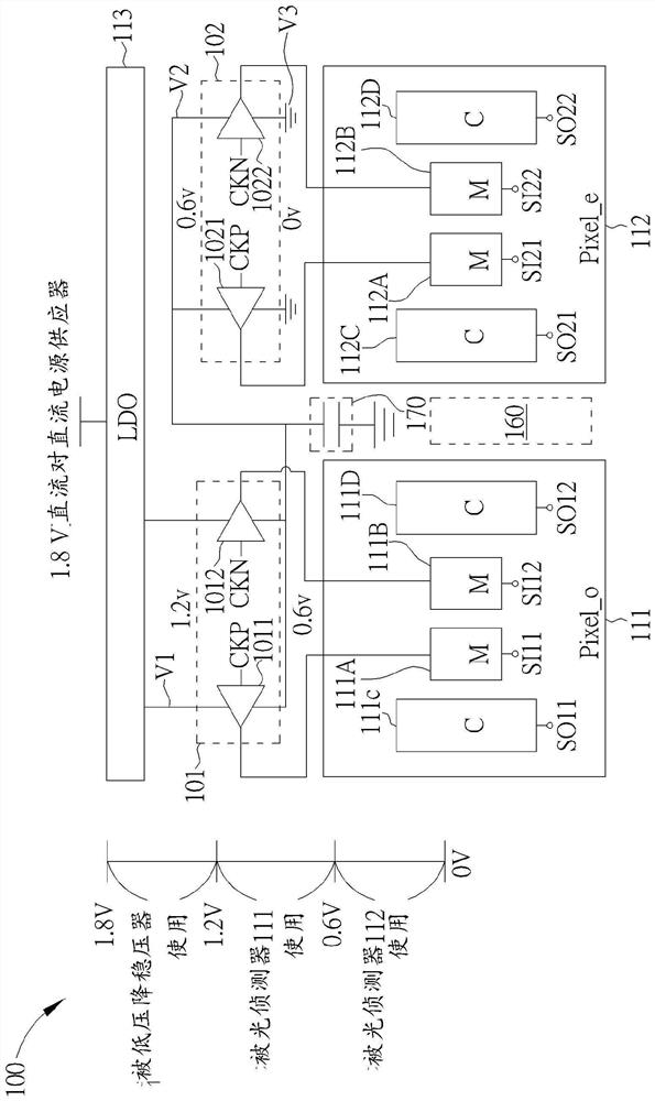
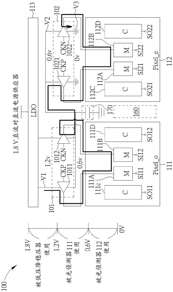
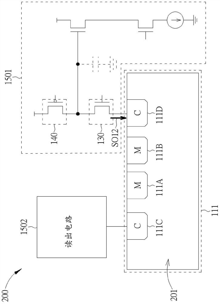
The invention discloses an photo-detecting apparatus and a current recycling method. The photo-detecting apparatus (100) includes a first photodetector (111), a second photodetector (112), a first modulation signal generating circuit (101) and a second modulation signal generating circuit (102). The first photodetector (111) is configured to generate at least a first detecting signal (SO11, SO12)according a first modulation signal (SI11, SI12). The second photodetector (112) is configured to generate a second detecting signal (SO21, SO22) according a second modulation signal (SI21, SI22). Thefirst modulation signal generating circuit (101) is coupled to the first photodetector (111) and operated between a first voltage (V1) and a second voltage (V2), and is configured to generate the first modulation signal (Sill, SI12). The second modulation signal generating circuit (102) is coupled to the second photodetector (112) and operated between the second voltage (V2) and a third voltage (V3). The second modulation signal generating circuit (102) is configured to generate a second modulation signal (SI21, SI22). The value of the second voltage (V2) is between the first voltage (V1) andthe third voltage (V3).

Description

technical field [0001] The present invention relates to time-of-flight (ToF) applications, in particular to an optical detection apparatus (apparatus) with a current reuse mechanism and a current reuse method. Background technique [0002] In a time-of-flight sensor, the light detector is a basic device, and can collectively form a pixel array to detect the arrival time of reflected light to determine the distance between the time-of-flight sensor and a target object distance between. Usually all photodetectors in the pixel array are directly coupled to a low-dropout voltage generated by a low-dropout (LDO) regulator, wherein the power of the low-dropout regulator Power consumption is determined based on its output voltage and load. Under this concept, when the time-of-flight ranging sensor requires a high-resolution pixel array, more photodetectors will need to be added under the low-dropout voltage regulator, which will continue to increase the overall power consumption....

Claims


Application Information

Patent Timeline
Patent Type & Authority Applications(China)
IPC IPC(8): G01S17/08H02M3/155
CPCG01S17/08H02M3/155G01S7/4863G01S7/4861G01S7/4913H01L27/14643H01L27/14609G01S7/4865
Inventor 梁哲夫
Owner ARTILUX INC
Why Eureka
Try Eureka