
Oil-gas mixed conveying system and working method thereof

A technology of oil and gas mixed transportation and working methods, applied in the direction of mixing methods, pipeline systems, chemical instruments and methods, etc., can solve problems such as shortening the service life of pumps, reducing production and stopping production, and dry burning of stators, so as to improve service life and save costs , to achieve the effect of the function

Inactive Publication Date: 2020-12-22
重庆明珠机电有限公司
View PDF6 Cites 1 Cited by
  • Summary
  • Abstract
  • Description
  • Claims
  • Application Information

AI Technical Summary

Problems solved by technology

[0003] At present, the screw pumps of many companies can realize the mixed transportation of oil and gas. The premise is that the pump’s liquid inlet needs to be evenly mixed with oil and gas. However, in actual oil transportation operations, the pump’s liquid inlet often only contains raw gas intermittently without crude oil. , in the absence of crude oil lubricating and cooling the stator, it is very easy to cause dry burning of the stator, which seriously shortens the service life of the pump, and even causes the adverse consequences of production reduction and shutdown of the user's production; based on the above situation, a solution to oil and gas is now considered Mixed-in implementation

Method used


Image

  • Oil-gas mixed conveying system and working method thereof
  • Oil-gas mixed conveying system and working method thereof
  • Oil-gas mixed conveying system and working method thereof

Examples


Embodiment Construction

[0033] The following will clearly and completely describe the technical solutions in the embodiments of the present invention with reference to the accompanying drawings in the embodiments of the present invention. Obviously, the described embodiments are only some, not all, embodiments of the present invention. Based on the embodiments of the present invention, all other embodiments obtained by persons of ordinary skill in the art without making creative efforts belong to the protection scope of the present invention.

[0034] In the description of the present invention, it should be noted that the orientation or positional relationship indicated by the terms "vertical", "upper", "lower" and "horizontal" are based on the orientation or positional relationship shown in the drawings, and are only for It is convenient to describe the utility and simplify the description, but does not indicate or imply that the device or element referred to must have a specific orientation, be con...


PUM


Abstract

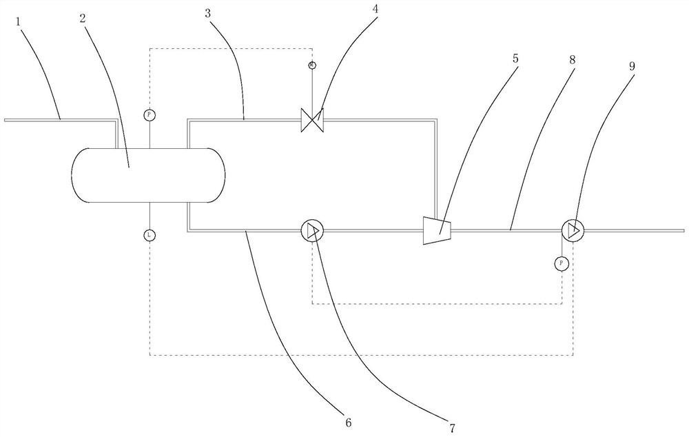
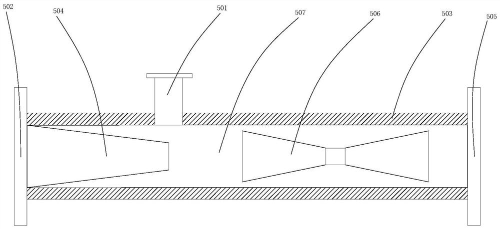
The invention discloses an oil-gas mixed conveying system. The system is provided with a mixed input pipe, wherein the output end of the mixed input pipe is connected with the input end of a gas-liquid separator, the gas-liquid separator is provided with a gas output port and a liquid output port, the gas output port is connected with one end of a gas conveying pipe, the gas conveying pipe is provided with a gas regulating valve, the other end of the gas conveying pipe is connected with a gas inlet of an ejector, the liquid output port is connected with one end of a liquid conveying pipe, theliquid conveying pipe is provided with a liquid conveying pump, the other end of the liquid conveying pipe is connected with a liquid inlet of the ejector, and the output end of the ejector is connected with a gas-liquid mixed conveying pump through a mixed output pipe. According to the system, separation, mixing, conveying, even heating and the like of crude oil and raw gas inflow liquid are integrated on one set of equipment, so that functions are diversified and integrated; and meanwhile, mixed conveying of crude oil and raw gas is realized, the phenomenon of stator dry-burning is avoided,the service life of the pumps is prolonged, and a large amount of cost is saved.

Description

technical field [0001] The invention relates to the technical field related to petroleum transportation, in particular to an oil and gas mixed transportation system and a working method thereof. Background technique [0002] At the current stage, oil and gas mixed transportation technology and equipment in the oil industry are in a very contradictory situation: on the one hand, the market demand is huge, and major oil fields must use oil and gas mixed transportation equipment to transport crude oil and raw gas; on the other hand, there is no perfect Stable and efficient oil and gas mixed transportation technology and equipment; [0003] At present, the screw pumps of many companies can realize the mixed transportation of oil and gas. The premise is that the pump’s liquid inlet needs to be evenly mixed with oil and gas. However, in actual oil transportation operations, the pump’s liquid inlet often only contains raw gas intermittently without crude oil. , in the absence of c...

Claims


Application Information

Patent Timeline
Patent Type & Authority Applications(China)
IPC IPC(8): F17D1/00F17D3/01B01F3/04
CPCF17D1/005F17D3/01B01F23/20
Inventor 马元张宁宁裴广济
Owner 重庆明珠机电有限公司
Learn More