Building heat preservation curtain wall structure

A technology for building thermal insulation and curtain wall, applied in building components, building structure, thermal insulation and other directions, can solve the problems of reduced thermal insulation effect, lack of thermal insulation function, threats to personnel life safety, etc., and achieve the effect of simple equipment structure

Active Publication Date: 2020-12-22
南京上柏建筑设计咨询有限公司
View PDF13 Cites 0 Cited by
  • Summary
  • Abstract
  • Description
  • Claims
  • Application Information

AI Technical Summary

Problems solved by technology

[0002] In the existing thermal insulation structure of buildings, since most of the curtain walls have the function of thermal insulation, and most of the curtain walls are installed from the external space, since the installation from the external space needs to be hung, this has caused personnel in the actual The reliability of installing the external curtain wall of the building is reduced, and the life safety of personnel is greatly threatened. It is precisely because of the existence of the above shortcomings that it is inconvenient for personnel to install the curtain wall, and because the thermal insulation properties of a single curtain wall are also low, It also makes the curtain wall lack the function of setting on one side of the curtain wall to insulate the curtain wall as a whole in the actual use process, which reduces the insulation effect of the equipment in the actual use process, and what is not effective is that it is more convenient for personnel to install and use the equipment , and difficult to maintain during subsequent use

Method used


Image

  • Building heat preservation curtain wall structure
  • Building heat preservation curtain wall structure
  • Building heat preservation curtain wall structure

Examples


Embodiment Construction

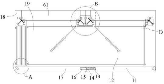
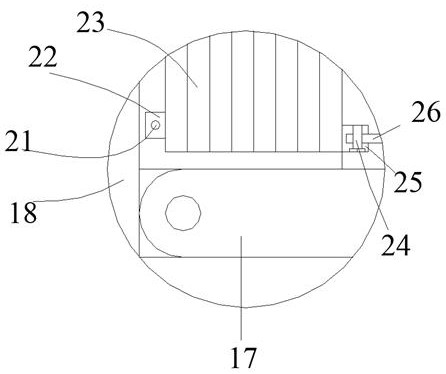
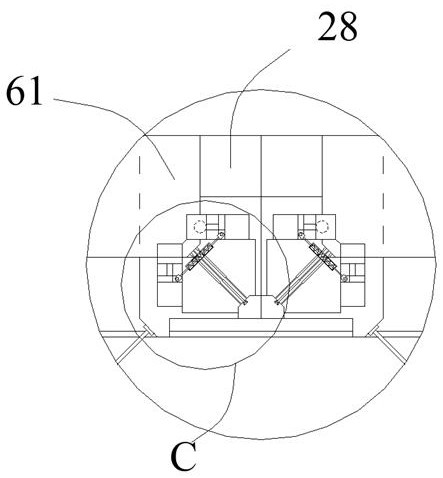
[0023] Such as Figure 1-Figure 5 As shown, the present invention is described in detail. For the convenience of description, the orientations mentioned below are now stipulated as follows: figure 1 The up, down, left, right, front and back directions of the projection relationship itself are consistent. A building thermal insulation curtain wall structure of the present invention includes a box body 18, and a side swing plate 17 and a swing plate 11 are arranged on the rear side of the box body 18. The side swing plate 17 and the swing plate The swing plate 11 is hingedly arranged with the box body 18, the box body 18 is provided with a cavity 19, and a locking device for locking each other is arranged between the side swing plate 17 and the swing plate 11, and the cavity 19 is provided with a thermal insulation device that can be pulled out to form a thermal insulation structure. A symmetrical matching plate 28 is provided in the cavity 19. A symmetrical curtain wall panel 6...


PUM


Abstract

The invention discloses a building heat preservation curtain wall structure. The building heat preservation curtain wall structure comprises a box body, wherein a side swing plate and a swing plate are arranged on the rear side of the box body, and the side swing plate and the swing plate are hinged to the box body; a containing cavity is formed in the box body, locking devices which are locked with each other are arranged between the side swing plate and the swing plate, and a heat preservation device which is pulled out to form a heat preservation structure is arranged in the containing cavity; symmetrical matching plates are arranged in the containing cavity, symmetrical curtain wall plates are arranged in the containing cavity, and clamping devices used for clamping the curtain wall plates are arranged on the two sides of the box body and one sides of the matching plates; and clamping rotation devices located on one sides of the matching plates and the matching plates are rotatablyarranged and driven by a motor to rotate. The building heat preservation curtain wall structure can be unfolded to form the inflated heat preservation structure to conduct heat preservation on the building heat preservation curtain wall structure, the function of automatically installing the curtain wall plates can be achieved, the danger coefficient of personnel is decreased, and the personnel can conveniently maintain the curtain wall plates.

Description

technical field [0001] The invention relates to the technical field of building thermal insulation equipment, in particular to a building thermal insulation curtain wall structure. Background technique [0002] In the existing thermal insulation structure of buildings, since most of the curtain walls have the function of thermal insulation, and most of these curtain walls are installed from the external space, since the installation from the external space needs to be hung, this has caused personnel in the actual The reliability of installing the external curtain wall of the building is reduced, and the life safety of personnel is greatly threatened. It is precisely because of the above shortcomings that it is inconvenient for personnel to install the curtain wall, and because the insulation properties of a single curtain wall are also low, It also makes the curtain wall lack the function of setting on one side of the curtain wall to insulate the curtain wall as a whole in t...

Claims


Application Information

Patent Timeline
IPC IPC(8): E04B1/76E04B1/80E04B2/88E04B2/92
CPCE04B1/76E04B1/806E04B2/88E04B2/92
Inventor 储小英
Owner 南京上柏建筑设计咨询有限公司
Why Eureka
Try Eureka