Magnetic control micro-pipeline
A micro-pipe and magnetron technology, applied in the field of micro-pipes, can solve the problems of inconvenient application of micro-fluidics, inconvenient micro-pipe diameter or conduction characteristics, etc., and achieve the effects of simple operation and high control precision.
- Summary
- Abstract
- Description
- Claims
- Application Information
AI Technical Summary
Problems solved by technology
Method used
Image
Examples
Embodiment 1
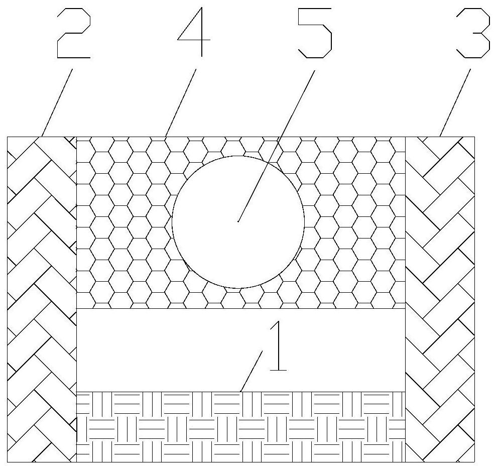
[0020] The invention provides a magnetically controlled micropipe. Such as figure 1 As shown, the magnetron micropipe includes an electromagnet 1 , a first iron yoke 2 , a second iron yoke 3 , and a magnetostrictive material part 4 . Two ends of the electromagnet 1 are respectively connected to one end of the first iron yoke 2 and one end of the second iron yoke 3 . The electromagnet 1 is used to generate a magnetic field, and the magnetic field generated by the electromagnet 1 can be adjusted by changing the current. The first iron yoke 2 and the second iron yoke 3 are used to conduct the magnetic field. Two ends of the magnetostrictive material part 4 are respectively fixedly connected to the other end of the first iron yoke 2 and the other end of the second iron yoke 3 . The material of the magnetostrictive material portion 4 is a magnetostrictive material. Holes are provided in the magnetostrictive material portion 4 to form micro-pipes 5 . Such as figure 1 As shown,...
Embodiment 2
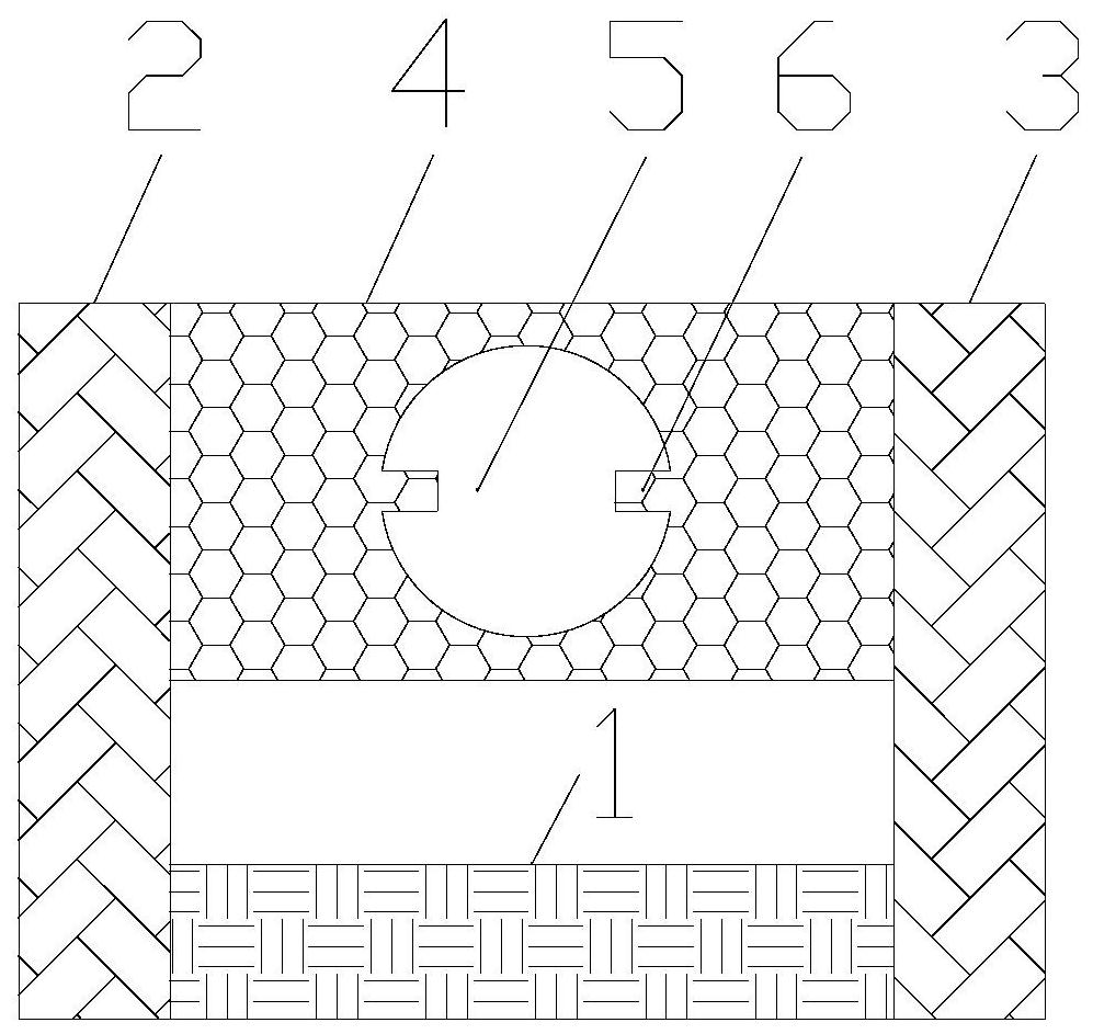
[0024] On the basis of Example 1, such as figure 2 As shown, a protrusion 6 is provided on the wall of the microchannel 5 . The material of the protrusion 6 is a magnetostrictive material. There are two protrusions 6 . The two protrusions 6 are arranged opposite to each other, and the direction of the line connecting the two protrusions 6 is the diameter direction of the micropipe 5 . The connection direction of the two protrusions 6 is parallel to the connection direction of the first iron yoke 2 and the second iron yoke 3 . The two protrusions 6 are not in contact. That is, if figure 2 As shown, the connecting line direction of the two protruding parts 6 is the horizontal direction, and the connecting line of the two protruding parts 6 is the diameter of the circular micropipe 5, and this direction is exactly under the action of the magnetic field, and the magnetostrictive material part 4 elongates or the direction of shrinkage. In this way, when the magnetic field i...
Embodiment 3
[0027] On the basis of Embodiment 1, the wall of the microchannel 5 is gear-shaped. In this way, when the magnetic field in the magnetostrictive material part 4 changes, the morphology of the wall of the micropipe 5 is changed more. Since the adsorption between the fluid in the microchannel 5 and the wall of the microchannel 5 is closely related to the shape of the wall of the microchannel 5, when the shape of the wall of the microchannel 5 changes, the conduction characteristics of the microchannel 5 will change more , so as to achieve higher sensitivity regulation of the conduction characteristics of the micropipe 5 .
PUM
 Abstract
Description
Claims
Application Information
 - R&D Engineer
- R&D Manager
- IP Professional
- Industry Leading Data Capabilities
- Powerful AI technology
- Patent DNA Extraction
Browse by: Latest US Patents, China's latest patents, Technical Efficacy Thesaurus, Application Domain, Technology Topic, Popular Technical Reports.
© 2024 PatSnap. All rights reserved.Legal|Privacy policy|Modern Slavery Act Transparency Statement|Sitemap|About US| Contact US: help@patsnap.com


