Experimental device and method for simulating multi-anchor coupling effect
A technology of experimental device and experimental method, which is applied in the direction of measuring device, using stable tension/compression to test the strength of materials, instruments, etc., can solve the problems that cannot accurately reflect the real influence of anchor rods on the surrounding soil, and achieve the benefit of Scientific research efficiency, disturbance reduction, and high precision effects
- Summary
- Abstract
- Description
- Claims
- Application Information
AI Technical Summary
Problems solved by technology
Method used
Image
Examples
Embodiment 1
[0050] Such as figure 1 As shown, the present embodiment provides a multi-anchor coupling experimental device, including a transparent model box 3, including a plurality of anchors parallel on the same vertical plane and inclined relative to the edge of the model box in the transparent model box 3. Rod 6; also includes an arc-shaped perforated strip 4 and an external loading device, the arc-shaped perforated strip 4 is provided with a plurality of perforations along the arc direction, and the arc of the arc-shaped perforated strip 4 is A part of a standard circle, and the arc is greater than or equal to 180 degrees, and the opening of the arc-shaped opening strip 4 faces the transparent model box 3 . Such as Figure 6 As shown, the anchor rod 6 is connected to the external loading device through the opening through the steel strand 5, and the external loading device controls the shrinkage of the steel strand; specifically, it is controlled by a pulley, that is, the upper and ...
Embodiment 2
[0057] This embodiment provides an experimental method for multi-anchor coupling, which is carried out in the experimental device for multi-anchor coupling described in Example 1, including the following steps:
[0058] 1) Use an oil-based pen to draw several uniform rectangular points on the glass plate 9 outside the model box for later image processing.
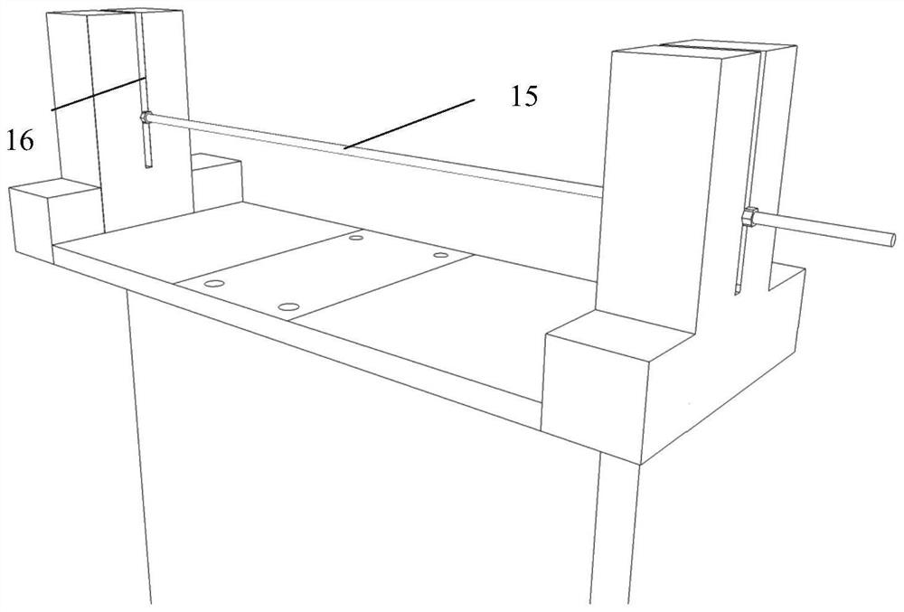
[0059] 2) Place the prefabricated backing plate with the same size as the bottom groove 8 of the model box in the bottom groove 8 of the model box, then place the movable baffle plate 7 of the transparent model box 3 according to the calculated size, and place the arc The strip base 18 of the shaped opening strip 4 is placed in the center of the movable baffle 7, aligned with the square opening, and fixed with bolts and nuts, and the height adjustment frame 16 on both sides of the movable baffle 7 is fine-tuned to make the overlap Adjust the bar 15 to the predetermined position, fill the soil in the transparent model box 3,...
PUM
 Abstract
Description
Claims
Application Information
 - Generate Ideas
- Intellectual Property
- Life Sciences
- Materials
- Tech Scout
- Unparalleled Data Quality
- Higher Quality Content
- 60% Fewer Hallucinations
Browse by: Latest US Patents, China's latest patents, Technical Efficacy Thesaurus, Application Domain, Technology Topic, Popular Technical Reports.
© 2025 PatSnap. All rights reserved.Legal|Privacy policy|Modern Slavery Act Transparency Statement|Sitemap|About US| Contact US: help@patsnap.com


