
A pressure relief and gas collection device for constant volume incendiary bombs

A technology of constant-volume incendiary bombs and gas-collecting devices, which can be used in measuring devices, internal combustion engine tests, engine tests, etc. It can solve the problems of unsatisfactory regulation and real-time change of unloading pressure, etc., and achieve the effect of high sealing performance

Active Publication Date: 2022-07-26
CHANGZHOU UNIV
View PDF8 Cites 0 Cited by
  • Summary
  • Abstract
  • Description
  • Claims
  • Application Information

AI Technical Summary

Problems solved by technology

This leads to the limitation of the pressure relief device, which cannot change the unloading pressure in real time and cannot satisfy the regulation of the pressure in the combustion chamber of the constant volume incendiary bomb during the experiment.

Method used


Image

  • A pressure relief and gas collection device for constant volume incendiary bombs

Examples


Embodiment Construction

[0014] The present invention will now be described in further detail with reference to the accompanying drawings. These drawings are all simplified schematic diagrams, and only illustrate the basic structure of the present invention in a schematic manner, so they only show the structures related to the present invention.

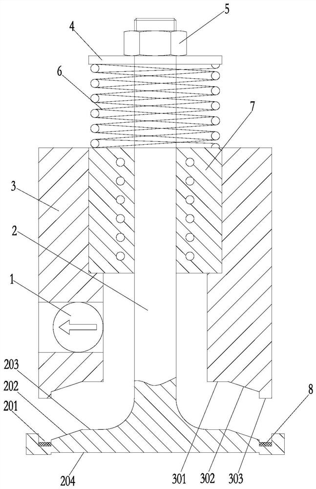
[0015] like figure 1 The shown pressure relief and gas collection device for constant volume incendiary bombs has a cylindrical base 3 made of austenitic stainless steel, and the interior of the base 3 is divided into upper, middle and lower parts. , wherein the upper and middle part of the base 3 forms a stepped through hole with a large upper and a lower small, and the lower end part of the base is a U-shaped structure, which is the function realization part of the device.

[0016] A linear bearing 7 is installed in the large hole of the step through hole of the base 3, the upper end face of the linear bearing 7 is aligned with the upper plane of the base...


PUM


Abstract

The invention relates to a pressure relief and gas collection device for a constant volume incendiary bomb, which has a base, a linear bearing is installed in the base, and an inverted T-shaped thimble push rod is slidably matched with the linear bearing. There is an air storage cavity in the base below the linear bearing, a one-way valve for discharging the gas in the air storage cavity is installed on the side wall of the base, a pressure plate is sleeved on the thimble push rod, and a reset is provided between the pressure plate and the upper end face of the linear bearing. When the external force pushes the thimble push rod downward, the inner side of the lower end of the thimble push rod is separated from the lower end surface of the base. When the external force disappears, the return spring pulls the thimble push rod upward and the inner side of the lower end of the thimble push rod is sealed and closed with the lower end surface of the base. The invention realizes the separation or closure of the inner side of the lower end of the ejector pin and the lower end surface of the base by applying pressure to the ejector pin push rod, controls the pressure maintenance and pressure relief of the combustion chamber of the constant volume incendiary bomb in real time, and releases the pressure after the end of the experiment. At the same time, it can also collect gas for later experimental steps such as gas analysis.

Description

technical field [0001] The invention relates to the technical field of internal combustion engines, in particular to a pressure relief and gas collection device for constant volume incendiary bombs. Background technique [0002] Constant volume incendiary bomb is an engine combustion simulation test device, which is based on the actual working conditions and working environment of the engine to simulate the specific process of fuel injection and combustion. It is necessary to establish a high temperature and high pressure test environment in the engine combustion chamber by changing the test parameters and test conditions under the same working conditions as the engine to improve the combustion efficiency and energy efficiency of the engine. Safety protection becomes the primary issue. [0003] Therefore, in order to solve the hidden dangers of constant volume incendiary bombs in high temperature and high pressure environment, it is necessary to add pressure relief devices ...

Claims


Application Information

Patent Timeline
Patent Type & Authority Patents(China)
IPC IPC(8): G01M15/02G01M15/04
CPCG01M15/02G01M15/04
Inventor 戴宇星张学飞倪志江周朝晖张国庆
Owner CHANGZHOU UNIV
Learn More