Eureka AIR delivers breakthrough ideas for toughest innovation challenges, trusted by R&D personnel around the world.

Skylight guide rail finish sawing machine gauge

A technology of precision sawing machine and guide rail, which is applied to the inspection tool field of skylight guide rail precision sawing machine, can solve the problems of non-uniform product cross-section, unguaranteed precision, non-uniform sawing length, etc., to improve detection efficiency, facilitate worker management, and facilitate The effect of data logging

Pending Publication Date: 2020-12-18
NINGBO MINTH AUTOMOTIVE PARTS RES&DEV CO LTD
View PDF0 Cites 0 Cited by
  • Summary
  • Abstract
  • Description
  • Claims
  • Application Information

AI Technical Summary

Problems solved by technology

As the size requirements of automotive steel parts become more and more stringent, the detection frequency and precision requirements for products are also getting higher and higher. The current sunroof guide rails have the following problems: the product cross-section is not uniform, and the sawing length is not uniform. Different products are customized with different inspection tools, and the inspection tools for inspecting products after sawing need to manually record data. One inspection tool for each product will cause tension in the site, and correspondingly increase management costs, resulting in waste of resources
The above detection methods have defects. 1. Customizing inspection tools for each product will increase manufacturing costs. Manually recording data will cause human factors to cause data errors, and the detection frequency cannot meet the requirements of the production line; 2. The accuracy of measuring products with a tape measure cannot Guaranteed, although the accuracy of the vernier caliper can be achieved, neither of these two tools can detect the verticality of the product after sawing; 3. CMM detection accuracy can be achieved, but the efficiency is not high, and the cost is relatively high

Method used


Image

  • Skylight guide rail finish sawing machine gauge
  • Skylight guide rail finish sawing machine gauge
  • Skylight guide rail finish sawing machine gauge

Examples


Embodiment Construction

[0022] Below in conjunction with specific embodiment, further illustrate the present invention. It should be understood that these examples are only used to illustrate the present invention and are not intended to limit the scope of the present invention. In addition, it should be understood that after reading the teachings of the present invention, those skilled in the art may make various changes or modifications to the present invention, and these equivalent forms also fall within the scope defined by the appended claims of the present application.

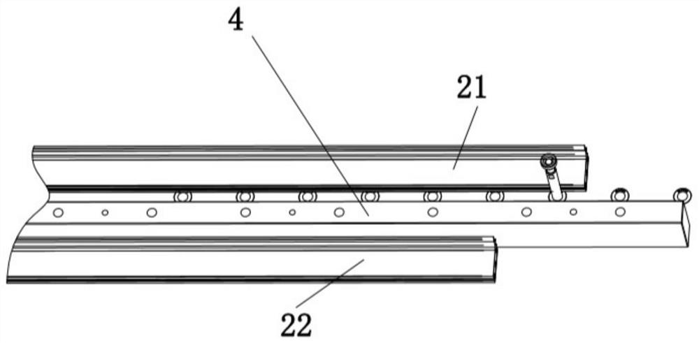
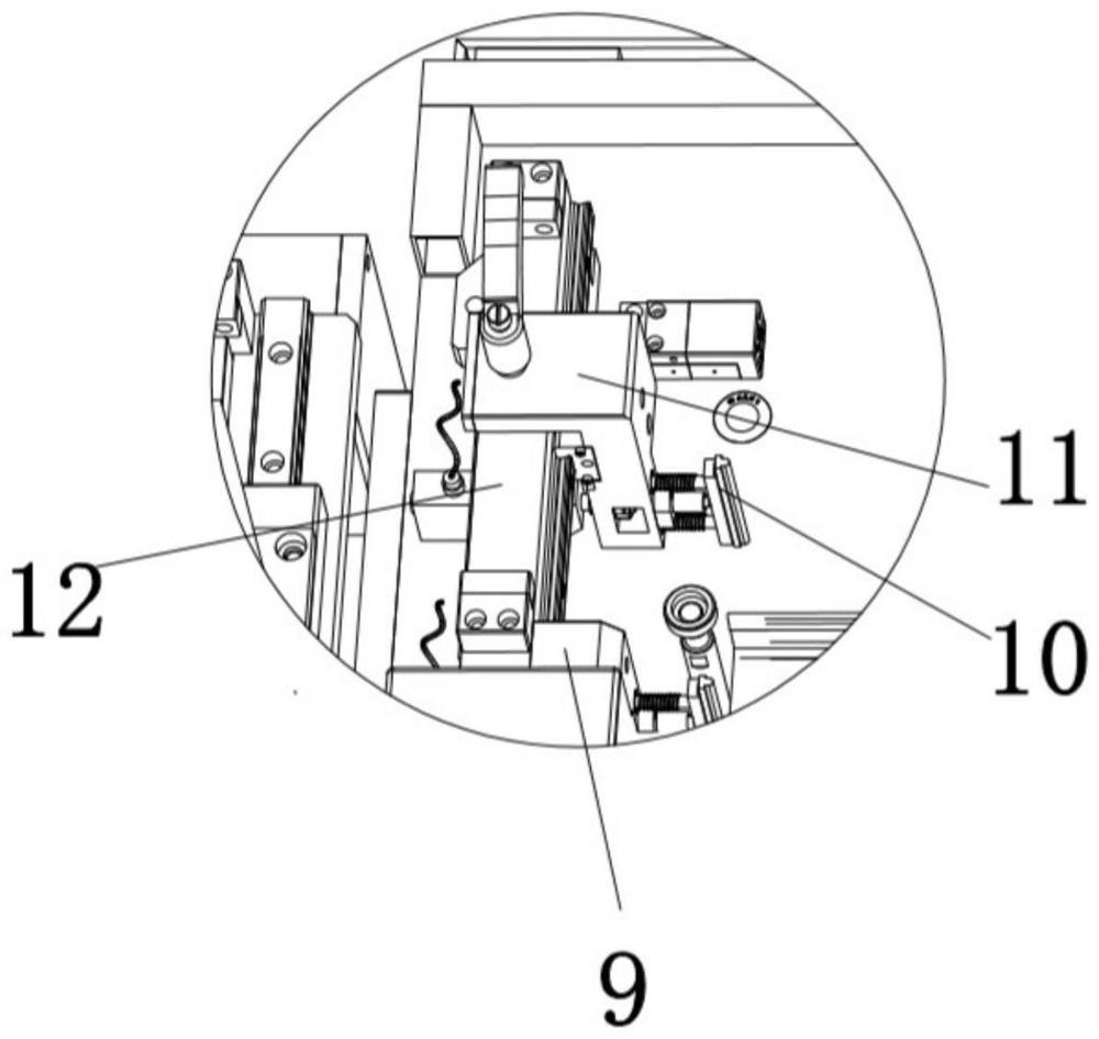
[0023] The embodiment of the present invention relates to a skylight guide rail fine saw machine inspection tool, such as figure 1 As shown in -2, when the technical solution was working, at first the preparatory work was carried out before the detection, and the positioning end sliding detection block 11 on the positioning end detection assembly 8, the translation end sliding detection block 20 on the translation end detection...


PUM


Abstract

The invention relates to a skylight guide rail finish sawing machine gauge which comprises a machine table, a positioning strip and a transverse sliding rail, the middle of the end face of the machinetable divides the end face of the machine table into a length detection face and a marking working face through the transversely-arranged positioning strip, and the two ends of the length detection face are provided with a positioning end detection assembly and a translation end detection assembly respectively. A transverse sliding rail is installed on the rear supplement edge of the length detection face of the machine table, an air cylinder positioning module connected with the translation end detection assembly is installed on the transverse sliding rail, and a marking machine corresponding to the marking working face is installed at the position, close to the installation positioning end detection assembly, of the machine table. The method has the advantages of simple operation, highdetection efficiency, convenient data recording, convenient management, good universality and the like.

Description

technical field [0001] The invention relates to the technical field of precise detection of skylight guide rails, in particular to a inspection tool for fine sawing machines of skylight guide rails. Background technique [0002] When conventional inspection tools detect steel products of auto parts, it is necessary to design matching inspection tools for each part of the inspection part to ensure the dimensional accuracy of the parts. As the size requirements of automotive steel parts become more and more stringent, the detection frequency and precision requirements for products are also getting higher and higher. The current sunroof guide rails have the following problems: the product cross-section is not uniform, and the sawing length is not uniform. Different products are customized with different inspection fixtures, and the inspection fixtures for inspecting products after sawing need to manually record data. One inspection fixture for each product will cause tension in...

Claims


Application Information

Patent Timeline
Patent Type & Authority Applications(China)
IPC IPC(8): G01B5/245G01B5/02G01B11/26G01B11/02
CPCG01B5/245G01B5/02G01B5/0025G01B11/26G01B11/02
Inventor 陈功
Owner NINGBO MINTH AUTOMOTIVE PARTS RES&DEV CO LTD
Why Eureka
Eureka Blog
Learn More