Bridge navigation aid indicator lamp

A technology of indicator lights and bridges, applied in the field of shipping, can solve problems such as difficult to identify lights of navigation aids on water, blurred vision, etc.

Inactive Publication Date: 2020-12-18
张荣祥
View PDF0 Cites 1 Cited by
  • Summary
  • Abstract
  • Description
  • Claims
  • Application Information

AI Technical Summary

Problems solved by technology

[0002] With the development of bridge construction technology, the span of navigable bridge holes has increased, and the volume of bridge piers in water has also increased. Some bridge piers adopt multi-stage caps. Obstacles, for this part of the protruding platform, there is no effective measure to prevent ships from colliding with it, and most of the bridg...

Method used


Image

  • Bridge navigation aid indicator lamp
  • Bridge navigation aid indicator lamp
  • Bridge navigation aid indicator lamp

Examples


Embodiment

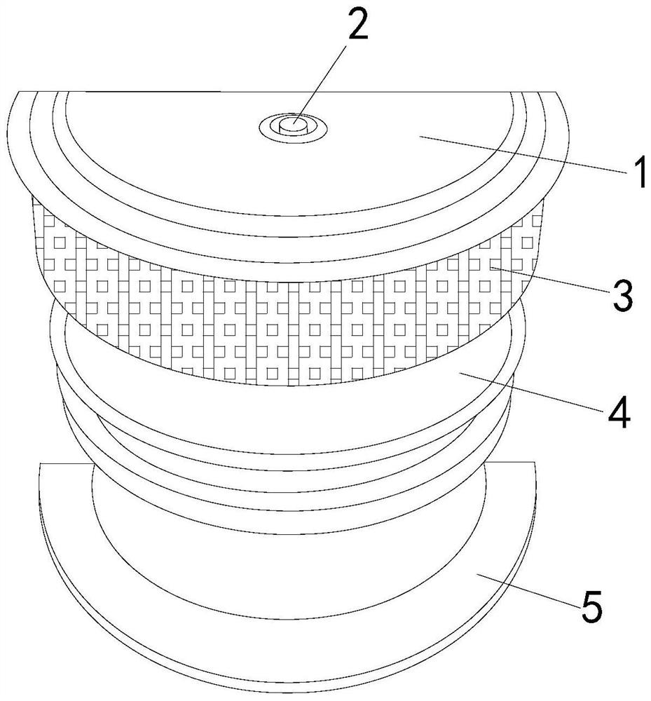
[0023] see figure 1 , the present invention provides a bridge navigation indicator light, the structure of which includes: a light frame 1, a switch 2, a light panel 3, an impact ring 4, and a base 5, the top of the light frame 1 is provided with a switch 2 and connected to it, and the light The plate 3 is located on the side of the light frame 1 and adjacent to the impact ring 4, and the two are connected to the outside of the light frame 1 in a circular manner. There is a base 5 under the light frame 1. The light frame 1 is in the shape of a semi-cylindrical structure, and its installation position is Planar structure, the position where the light emits outwards presents a semi-circular arc surface structure, which helps the light to irradiate the water surface in a fan-shaped range at an angle of 180 degrees, increases the light irradiation area, and reduces the blind spot of light irradiation , the switch 2 adopts a push-type pneumatic closing structure to control the ope...

Embodiment 2

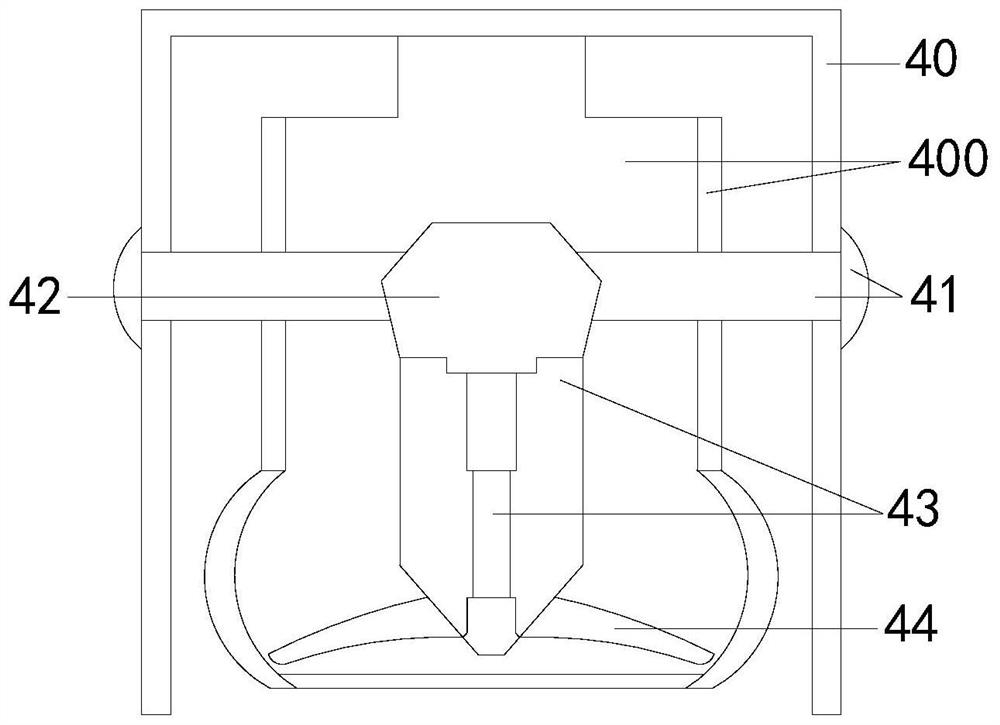
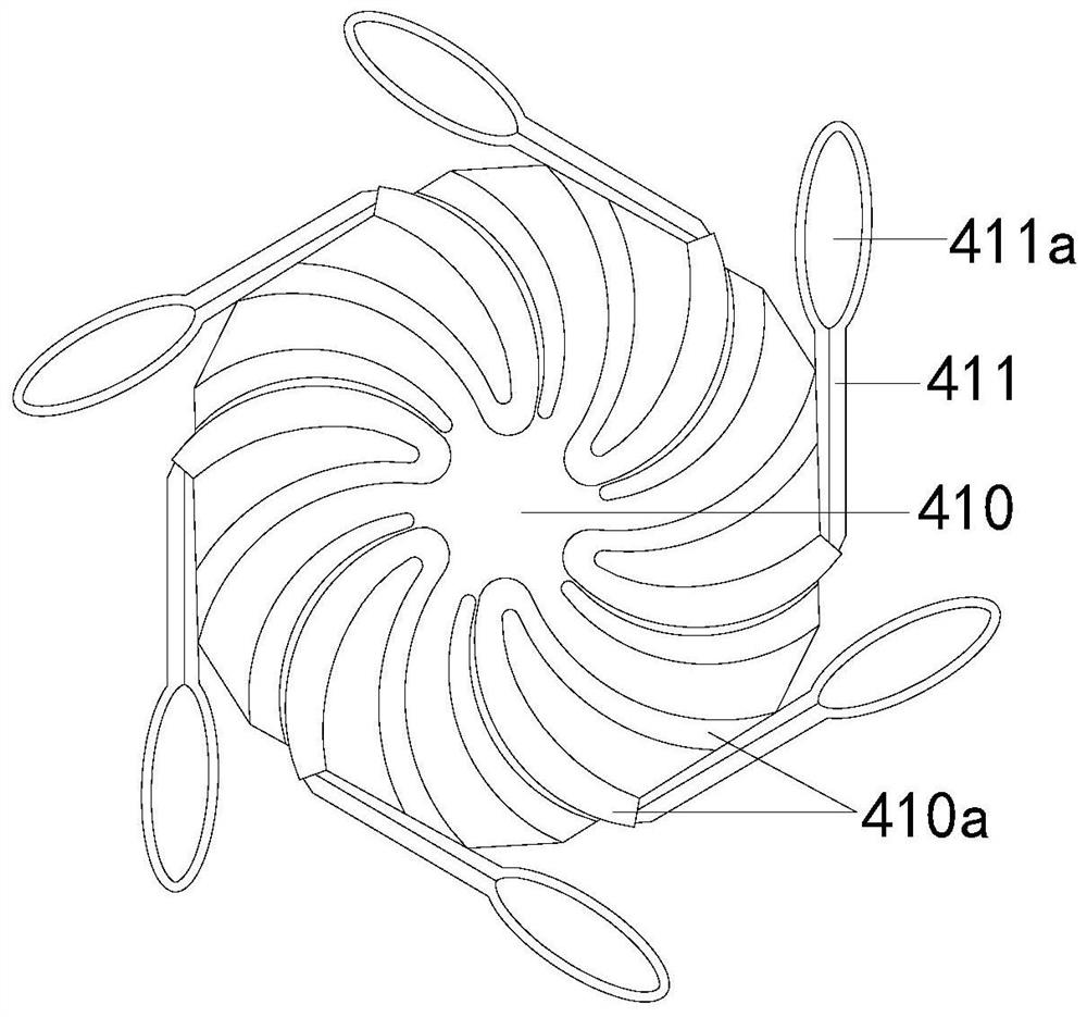
[0029] The description of the second embodiment drawn in conjunction with the first embodiment, combined with image 3 , Figure 4 , the sides of the hexagonal capsule body 410 are distributed in a hexagonal arrangement and connected to the rolling rollers 411, the cavity 420 and the flapping capsule 422 are connected to each other with a flapping capsule 422, and the flapping capsules 422 are connected to each other. Connected, the back of the light frame 1 is installed horizontally with the side of the bearing platform, and the light board 3 faces the return direction of the flight line, and the bottom of the equipment extends below the water surface. When the water flow contacts the scroll roller 411 in a flowing state, it will produce a force conversion In order to drive the rotation power of the hexagonal capsule 410, the water flow is continuously inhaled to fill the lung cavity 42 under the drive of the rotation power. At the same time, the external water flow disturban...


PUM


Abstract

The invention discloses a bridge navigation aid indicator lamp. The bridge navigation aid indicator lamp structurally comprises a lamp holder, a switch, a lamplight plate, an impact ring and a base, wherein the top end of the lamp holder is provided with the switch and is connected with the switch, the lamplight plate is located on the side edge of the lamp holder and adjacent to the impact ring,and the lamplight plate and the impact ring are connected to the exterior of the lamp holder in an annular mode, and the base is arranged below the lamp holder. The bridge navigation aid indicator lamp has the beneficial effects that the bridge navigation aid indicator lamp is arranged at the position of a bearing platform on the water surface by using the impact ring, so that the bridge navigation aid indicator lamp is half-exposed out of the water surface, and meanwhile vibration waves generated when the structure makes contact with water flow serve as an energy supplementing mode generatedby the combined action of the lamplight plate and the water flow, and the water flow and water waves impact a beating bag structure so that the fuzzy degree of the water waves covering the lamplight plate can be effectively reduced, and the marked identification degree of the bearing platform on the water surface is enhanced.

Description

technical field [0001] The invention relates to the field of shipping, in particular to a bridge navigation indicator light. Background technique [0002] With the development of bridge construction technology, the span of navigable bridge holes has increased, and the volume of bridge piers in water has also increased. Some bridge piers adopt multi-stage caps. Obstacles, for this part of the protruding platform, there is no effective measure to prevent ships from colliding with it, and most of the bridges currently built are built near the urban area and the port area. The impact is very large. Under the condition of water waves hitting the lights, the vision of ship pilots is blurred and it is difficult to recognize the lights of the navigation aids on the water. Based on the above premise, this case developed a bridge navigation indicator to solve this problem. Contents of the invention [0003] Aiming at the deficiencies of the prior art, the present invention is reali...

Claims


Application Information

Patent Timeline
IPC IPC(8): F21S9/03F21S9/04F21V15/04F21V21/02E02B3/26F21W111/04
CPCE02B3/26F21S9/03F21S9/046F21V15/04F21V21/02F21W2111/04Y02A30/30
Inventor 张荣祥
Owner 张荣祥
Why Eureka
Try Eureka