
Cutter clamping device for detection

A clamping device and tool clamping technology, used in workpiece clamping devices, lighting devices, lighting devices, etc., can solve the problems of error in observation results, cumbersome operation, low efficiency, etc., to improve accuracy and versatility, guarantee multi-angle effect

Inactive Publication Date: 2020-12-18
GUANGZHOU UNIVERSITY
View PDF4 Cites 0 Cited by
  • Summary
  • Abstract
  • Description
  • Claims
  • Application Information

AI Technical Summary

Problems solved by technology

[0003] At present, the commonly used method of observing tool wear is to observe the tool through a microscope, which can easily obtain key information such as wear width and wear area, but the wear of the tool is usually not concentrated on a specific position on a certain knife face And when acquiring the image of tool wear information, the observation angle of the microscope itself is very limited, so it is usually necessary to change multiple observation angles and perform multiple observations to complete this work
[0004] The existing fixtures are usually cumbersome when changing the position and angle of the tool, resulting in low efficiency, and if the adjustment of the larger angle and position is performed, the accuracy and stability of the tool position cannot be guaranteed. The position of the microscope lens may affect the focus of the lens. If you want to compare the wear of the same tool at different stages and multiple tools at the same position, it is impossible to ensure sufficient position accuracy during the re-clamping process of the tool. These problems will bring certain errors to the observation results, and will also increase the complexity and difficulty of result comparison

Method used


Image

  • Cutter clamping device for detection
  • Cutter clamping device for detection
  • Cutter clamping device for detection

Examples


Embodiment Construction

[0022] This part will describe the specific embodiment of the present invention in detail, and the preferred embodiment of the present invention is shown in the accompanying drawings. Each technical feature and overall technical solution of the invention, but it should not be understood as a limitation on the protection scope of the present invention.

[0023] In the description of the present invention, it should be understood that the orientation descriptions, such as up, down, front, back, left, right, etc. indicated orientations or positional relationships are based on the orientations or positional relationships shown in the drawings, and are only In order to facilitate the description of the present invention and simplify the description, it does not indicate or imply that the device or element referred to must have a specific orientation, be constructed and operated in a specific orientation, and thus should not be construed as limiting the present invention.

[0024] I...


PUM


Abstract

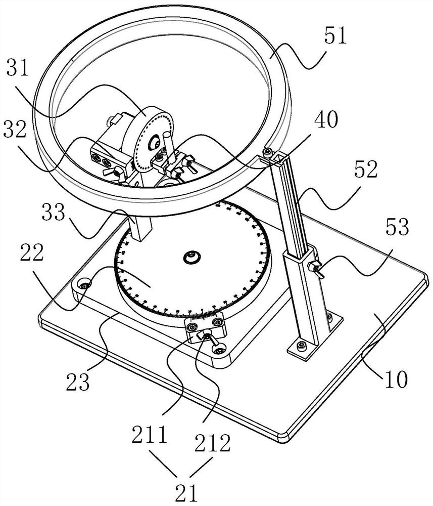
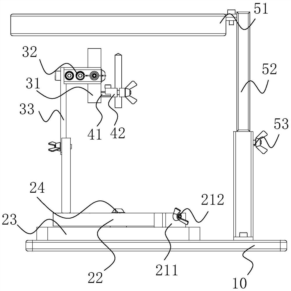
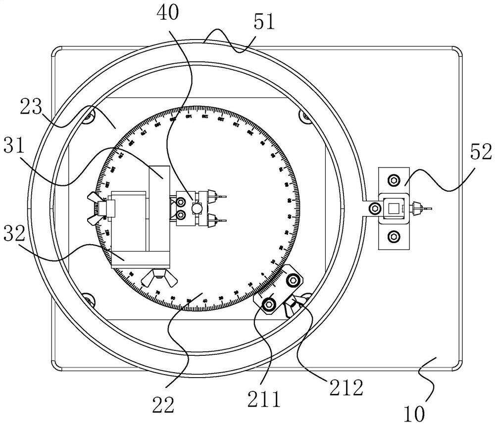
The invention discloses a cutter clamping device for detection. The cutter clamping device comprises a base, an XY plane adjusting device, a first support, a YZ plane adjusting device and a cutter clamping assembly, wherein the XY plane adjusting device comprises a first rotary disc and a first locking assembly, and the first locking assembly is in contact with the first rotary disc; the first support is eccentrically arranged on the first rotary disc; the YZ plane adjusting device comprises a second rotary disc and a second locking assembly, the center line of the second rotary disc is perpendicular to the center line of the first rotary disc, and the second locking assembly is in contact with the second rotary disc; and the cutter clamping assembly is eccentrically arranged on the secondrotary disc. According to the cutter clamping device for detection, a cutter to be detected is clamped through the cutter clamping assembly, the XY plane angle and the YZ plane angle of the cutter clamping assembly are adjusted through the XY plane adjusting device and the YZ plane adjusting device, the cutter clamping assembly is always kept in the center of a clamp in the adjusting process, thehorizontal position of the cutter clamping assembly does not need to be adjusted again, the trouble that the observation position of a lens needs to be adjusted after the position of the cutter is changed is avoided, the observation accuracy of the cutter is guaranteed, and the universality of the cutter clamping device is improved.

Description

technical field [0001] The invention relates to the field of tool detection tools, in particular to a tool clamping device for detection. Background technique [0002] After a period of drilling and other processing methods, the cutter face and cutting edge will be worn to a certain extent, which will affect the processing accuracy of the product later. If it is necessary to analyze the impact of tool wear on the workpiece, it is necessary to repeat it accurately. Observe and obtain the wear conditions of the lower cutter face at different angles, such as the change of the wear area. [0003] At present, the commonly used method of observing tool wear is to observe the tool through a microscope, which can easily obtain key information such as wear width and wear area, but the wear of the tool is usually not concentrated on a specific position on a certain knife face Moreover, the observation angle of the microscope itself is very limited when obtaining images of tool wear i...

Claims


Application Information

Patent Timeline
Patent Type & Authority Applications(China)
IPC IPC(8): B25B11/00B25H1/10F21V33/00
CPCB25B11/00B25H1/10F21V33/00
Inventor 朱萍玉蒋笑楠张楠张浩钰
Owner GUANGZHOU UNIVERSITY
Learn More