
Automatic detection system and method thereof

A technology of automatic detection and detection area, which is used in measurement devices, material analysis by optical means, instruments, etc., which can solve the problems of missed inspection, prolonged detection time, and reduced production capacity.

Pending Publication Date: 2020-12-15
TUL CORP
View PDF0 Cites 0 Cited by
  • Summary
  • Abstract
  • Description
  • Claims
  • Application Information

AI Technical Summary

Problems solved by technology

However, in the above-mentioned manual inspection method, there are often cases of missed inspections, resulting in the occurrence of defective products that are not detected.
In addition, the manual inspection method will lead to longer inspection time, which will lead to a decrease in production capacity

Method used


Image

  • Automatic detection system and method thereof
  • Automatic detection system and method thereof
  • Automatic detection system and method thereof

Examples


Embodiment Construction

[0043] The implementation of the present invention will be described in more detail below with reference to the drawings and reference numerals, so that those skilled in the art can implement it after studying this specification.

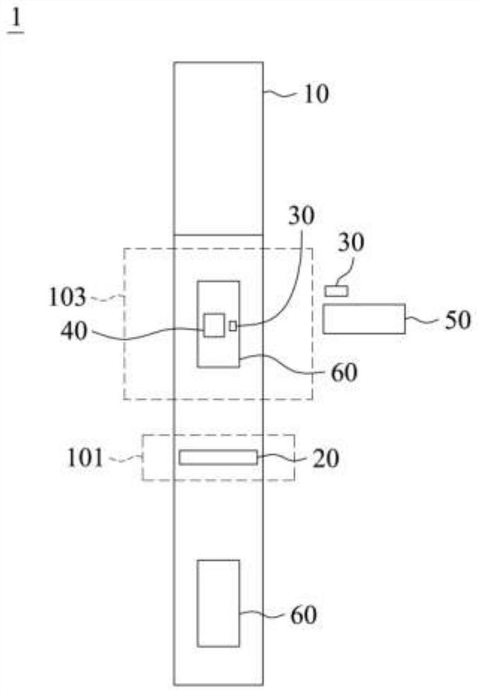
[0044] figure 1 It is a schematic top view for illustrating the structure of an automatic detection system according to an embodiment of the present invention. Please refer to figure 1 , in one embodiment of the present invention, the automatic detection system 1 includes a production line 10, at least one sensor 20, at least one supplementary light element 30, a first photographing device 40, a second photographing device 50, and a computer device ( not shown in the figure).

[0045] The production line 10 includes a sensing area 101 and a detection area 103 . At least one sensor 20 is set at a position adjacent to the production line 10 at the sensing area 101, such as above, on the side of the production line 10, etc., in the figure 1 Middle ...


PUM


Abstract

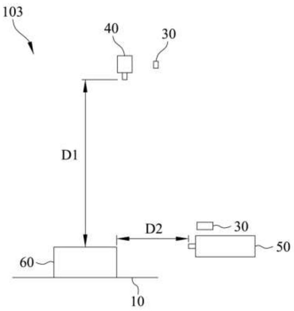
An automatic detection system comprises a production line which comprises an induction area and a detection area; at least one sensor which is used for sensing at least one to-be-detected object conveyed by the production line; at least one light supplementing element which is arranged above and / or on the side edge of the production line in the detection area; a first photographic device which isarranged above the production line at a first distance in the detection area, and the first photographic device acquires an upper state picture of the at least one to-be-detected object; a second photographic device which is arranged on the side edge of the production line at a second distance in the detection area, and the second photographic device acquires a side edge state picture of the at least one to-be-detected object; and a computer device which is used for receiving the upper state picture and the side edge state picture and carrying out image identification on the upper state picture and the side edge state picture.

Description

technical field [0001] The present invention is an automatic detection system and detection method, specifically, an automatic detection system and method for detecting the installation status of components of various electronic products through image recognition. Background technique [0002] The display card is one of the most basic components of a personal computer device. Its purpose is to convert the display information required by the computer system to drive the display, and to provide progressive or interlaced scanning signals to the display to control the correct display of the display. An important component of the motherboard of a personal computer, and one of the important devices of "human-machine dialogue". Furthermore, the field programmable logic gate array (Field Programmable Gate Array, FPGA) is a product further developed on the basis of programmable logic devices such as PAL, GAL, and CPLD. It appeared as a semi-customized circuit in the field of special...

Claims


Application Information

Patent Timeline
Patent Type & Authority Applications(China)
IPC IPC(8): G01N21/01
CPCG01N21/01G01N2021/0181
Inventor 陈剑威贾博渊
Owner TUL CORP
Learn More