Bottom oil removing device

A technology for removing device and sinking oil, which is used in general water supply conservation, open water surface cleaning, water conservancy projects, etc. It can solve problems such as high requirements for professional operation, affecting channel conditions, and large amount of oil pollution, and achieve sea surface operation time. Short, easy to understand assembly, small oil pollution area

Pending Publication Date: 2020-12-15
CHINA WATERBORNE TRANSPORT RES INST
View PDF0 Cites 0 Cited by
  • Summary
  • Abstract
  • Description
  • Claims
  • Application Information

AI Technical Summary

Problems solved by technology

One is manual collection by divers. This method requires divers to directly contact with oil pollution. The operation requires high professionalism and is dangerous and inefficient. No practical reports have been seen so far.
The second is the marine towline, which is suitable for shallow seas. The scraping of the bottom of the seabed and the disturbance of the water body will cause damage to a large area of ​​the seabed ecosystem. The oil pollution is swept to other seabed areas or causes the sinking oil to float up again to form semi-submersible oil, which expands the polluted area; in addition, this method requires a high degree of cooperation between the ship and the operator, and the cost and professionalism of the operator are high.
Moreover, this method will affect the channel conditions and is not suitable for navigation in busy sea areas
The third is the pump suction system, which can be applied to deep sea areas and basically does not require direct contact between divers and oil pollution. However, this method is expensive and has high professional requirements for operators, and it will cause indiscriminate suction of oil pollution and bottom quality on the seabed. Destroy the seabed ecosystem and the navigation conditions of the channel; the large amount of oil-water mixture recovered by the pumping system will greatly increase the follow-up pollutant disposal work and cost of the clean-up action; Large) or large-area aggregated submarine oil pollution (multiple small-scale oil pollution, not far from each other)

Method used


Image

  • Bottom oil removing device
  • Bottom oil removing device
  • Bottom oil removing device

Examples


Embodiment Construction

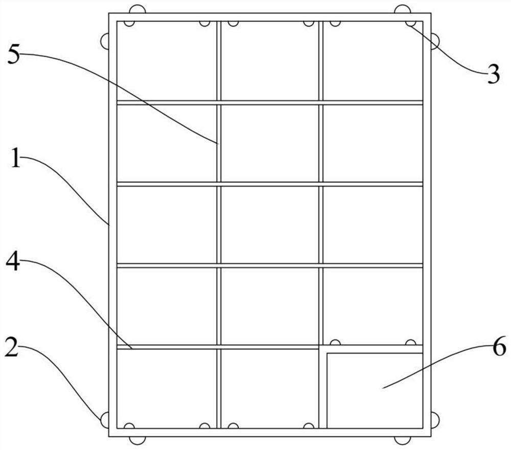
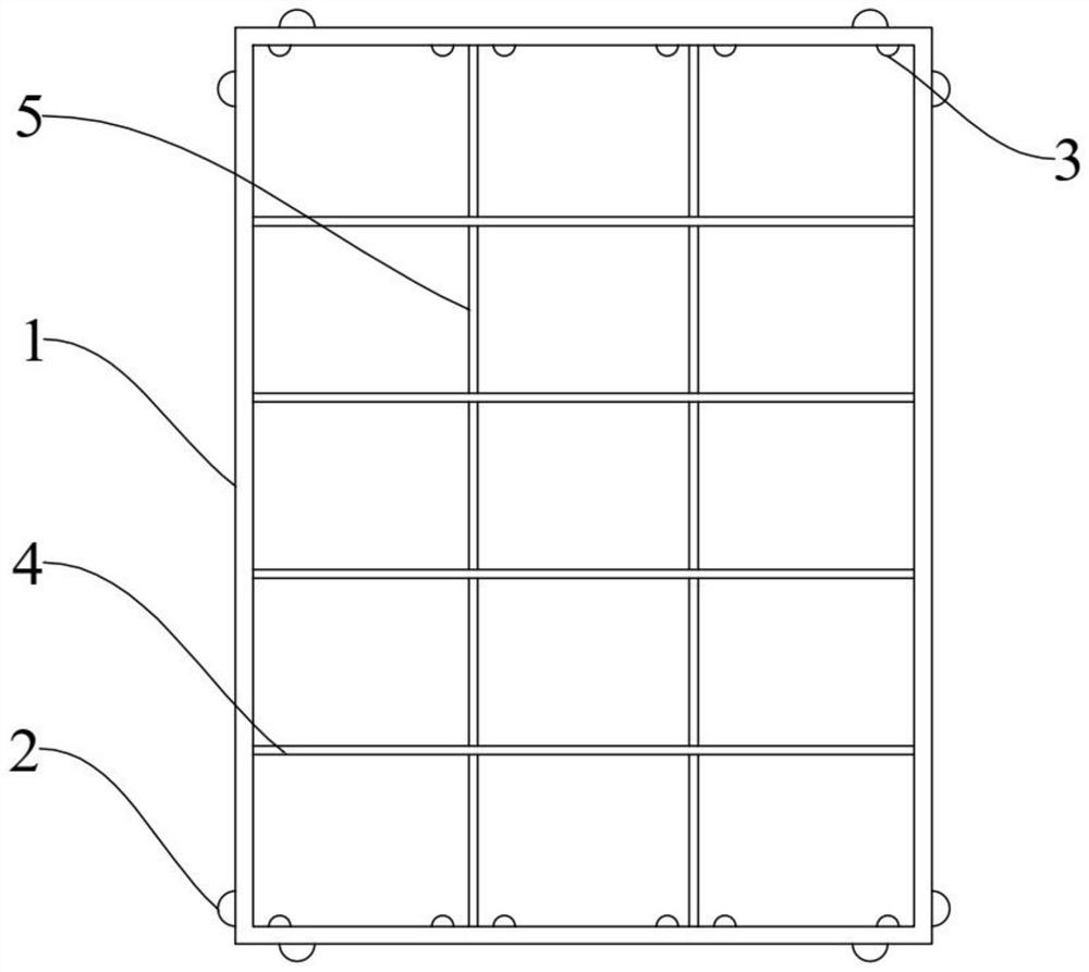
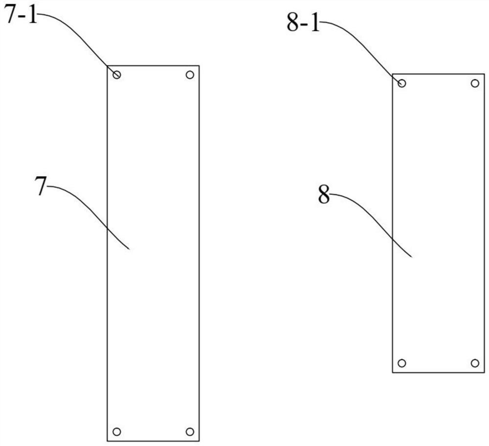
[0067] Embodiments of the present invention are described in detail below, examples of which are shown in the drawings, wherein the same or similar reference numerals designate the same or similar elements or elements having the same or similar functions throughout. The embodiments described below by referring to the figures are exemplary and are intended to explain the present invention and should not be construed as limiting the present invention.

[0068] In describing the present invention, it is to be understood that the terms "upper", "lower", "front", "rear", "left", "right", "vertical", "horizontal", "top", The orientation or positional relationship indicated by "bottom", "inner", "outer", etc. is based on the orientation or positional relationship shown in the drawings, and is only for the convenience of describing the present invention and simplifying the description, rather than indicating or implying the referred device or positional relationship. Elements must hav...


PUM


Abstract

The invention discloses a bottom oil removing device. The bottom oil removing device comprises one or more modules and one or more floating positioning devices; the modules comprise supports and adsorption cotton pieces; the adsorption cotton pieces are located in the supports and connected with the supports; the adjacent supports are connected with one another, so that the multiple modules extendin the horizontal direction; and the floating positioning devices are mounted in the supports. The bottom oil removing device provided by the invention is low in operation technical requirement, is less limited by severe sea conditions, has the small influence on marine environment (seabed sediments, the channel water depth and the like), has high pertinence on removing work of small-area bottomoil in scattered distribution, and is large in oil adsorption area, higher in bottom oil capturing capacity and firmer in adhesion.

Description

technical field [0001] The invention relates to the technical field of environmental protection, in particular to a bottom oil removal device. Background technique [0002] With the sustained and rapid economic and social development, my country's energy demand and crude oil imports are increasing year by year. Ship traffic accidents, pipeline leakage of submarine and coastal oil storage facilities, drilling platform leakage, or salvage of sunken ships may cause oil leakage accidents. After the oil leaks into the sea, its density may change due to the natural environment and human intervention, or it may be suspended in the sea water or sink to the seabed (it will be resuspended when disturbed), forming submerged oil. Submersible oil is often found in shallow seas, especially in semi-enclosed bays. [0003] Submersible oil includes semi-submersible oil and bottom oil. Among them, the oil suspended in seawater and drifting with the current is called semi-submersible oil. S...

Claims


Application Information

Patent Timeline
Patent Type & Authority Applications(China)
IPC IPC(8): E02B15/04E02B3/02
CPCE02B3/023E02B15/04Y02A20/204
Inventor 石敬陈荣昌
Owner CHINA WATERBORNE TRANSPORT RES INST
Why Eureka
Try Eureka