Novel wire clamping device wire pressing mechanism

A thread gripper and thread crimping technology, which is applied in the field of new thread gripper crimping mechanism, can solve problems such as thread gripper looseness, thread supply of thread take-up lever is small, affect work efficiency, etc., achieve uniform force balance, improve Improve embroidery quality and improve efficiency

Pending Publication Date: 2020-12-15
浙江兆山机电有限公司
View PDF6 Cites 1 Cited by
  • Summary
  • Abstract
  • Description
  • Claims
  • Application Information

AI Technical Summary

Problems solved by technology

When the existing thread clamp is in use, because the embroidery thread keeps passing through the thread clamp, the thread clamp often becomes loose and the thread clamp loses its ability to clamp the thread.
Since the existing upper thread tension adjustment is realized by manually adjusting the thread pressing nut, there are different upper thread tensions in each machine head, which may cause the upper thread to not be tightened tightly and the upper thread tension to be too large. The thread breakage problem caused by the thread supply of the thread take-up lever is less than the consumption of the upper thread
This just makes workers need to repeatedly wire and adjust the crimping nut, which not only affects work efficiency, but also affects the quality of embroidery; on this basis, the applicant proposes further improvements and designs a new thread clamp crimping mechanism to meet existing market needs

Method used


Image

  • Novel wire clamping device wire pressing mechanism
  • Novel wire clamping device wire pressing mechanism
  • Novel wire clamping device wire pressing mechanism

Examples


Embodiment Construction

[0024] The preferred embodiments of the present invention will be described below in conjunction with the accompanying drawings. It should be understood that the preferred embodiments described here are only used to illustrate and explain the present invention, and are not intended to limit the present invention.

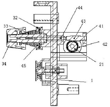
[0025] Such as Figure 1-4 As shown, the present invention is a novel wire clamp mechanism, including a wire clamp seat 1, characterized in that it also includes a control device, a wire clamp structure, and an adjustment device connected to the control device. The present invention drives the turbine 42 through the micro-motor 21 and connects the worm 43. The worm 43 will produce a slight movement distance before and after. At the moment of thread trimming, the micro-motor 21 is electronically controlled to drive the ejector rod main body 44 to release the pressure of the clamping bowl 32, so that the upper thread can be pulled out 30-55MM thread smoothly, so that ...


PUM


Abstract

The invention discloses a novel wire clamping device wire pressing mechanism. The wire pressing mechanism comprises a wire pressing device seat and is characterized by further comprising a control device, a wire clamping structure and an adjusting device connected with the control device. The wire pressing mechanism can overcome the defects in the prior art, and is simple in structure, safe to use, balanced and uniform in stress, capable of improving the efficiency and beneficial to improving the embroidery quality.

Description

technical field [0001] The invention relates to a novel thread pressing mechanism of a thread gripper. Background technique [0002] Computerized embroidery machine is the most advanced embroidery machine in the contemporary era. It can achieve high-speed and high-efficiency traditional manual embroidery, and can also achieve "multi-level, multi-functional, uniform and perfect" that cannot be achieved by manual embroidery. Requirements, it is an electromechanical product that embodies a variety of high-tech. The thread clamp assembly is an important part in the computerized embroidery machine. It mainly divides, clamps and tensions the embroidery thread through the thread passing wheel, detection wheel and thread clamp installed on the thread clamp installation panel. Important device for adjustment. When the existing thread gripper is in use, because the embroidery thread keeps passing through the thread gripper, the thread gripper often becomes loose and the thread gripp...

Claims


Application Information

Patent Timeline
IPC IPC(8): D05C11/08
CPCD05C11/08
Inventor 魏章淼何纪江
Owner 浙江兆山机电有限公司
Why Eureka
Try Eureka