
Computer host structure for computer teaching

A computer and teaching technology, applied in the computer field, can solve the problems of reduced heat dissipation capacity and burning loss of electrical components, and achieve the effect of improving heat dissipation effect, ensuring smooth operation and ensuring service life.

Inactive Publication Date: 2020-12-11
ZIBO VOCATIONAL INST
View PDF0 Cites 2 Cited by
  • Summary
  • Abstract
  • Description
  • Claims
  • Application Information

AI Technical Summary

Problems solved by technology

[0003] At present, the existing computer hosts mostly use fixed-point fans for heat dissipation. This cooling method requires the computer host to be equipped with open vents, which causes a large amount of air to float and sink into the computer host as the fan works, and a large amount of floating dust covers the air. On the electrical components, the heat dissipation capacity of the electrical components is greatly reduced, and even the phenomenon of burning occurs

Method used


Image

  • Computer host structure for computer teaching
  • Computer host structure for computer teaching
  • Computer host structure for computer teaching

Examples


Embodiment 1

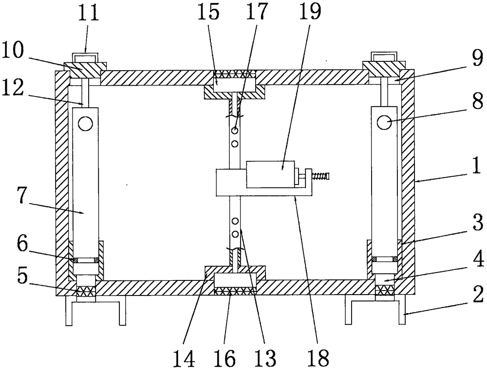
[0031] See figure 1 , a computer host structure for computer teaching, comprising a chassis 1, the left and right sides of the bottom of the chassis 1 are symmetrically provided with legs 2, the legs 2 are U-shaped frame structures, and the legs 2 are used to support the chassis 1, thereby ensuring The stability of the placement of the chassis 1;

[0032] The left and right sides of the inner cavity bottom wall of the cabinet 1 are symmetrically provided with air intake cylinders 3, which correspond to the legs 2 in the vertical direction. The air intake cylinders 3 are cylindrical structures with an open top, and the air intake cylinders The bottom end of 3 connects the support foot 2 through the air inlet 4, the first protective net 5 is arranged in the air inlet 4, the inner cavity of the air inlet cylinder 3 is provided with a support plate 6, and the support plate 6 It is a ring-shaped structure, and the top end of the air intake cylinder 3 is threadedly connected with a...

Embodiment 2

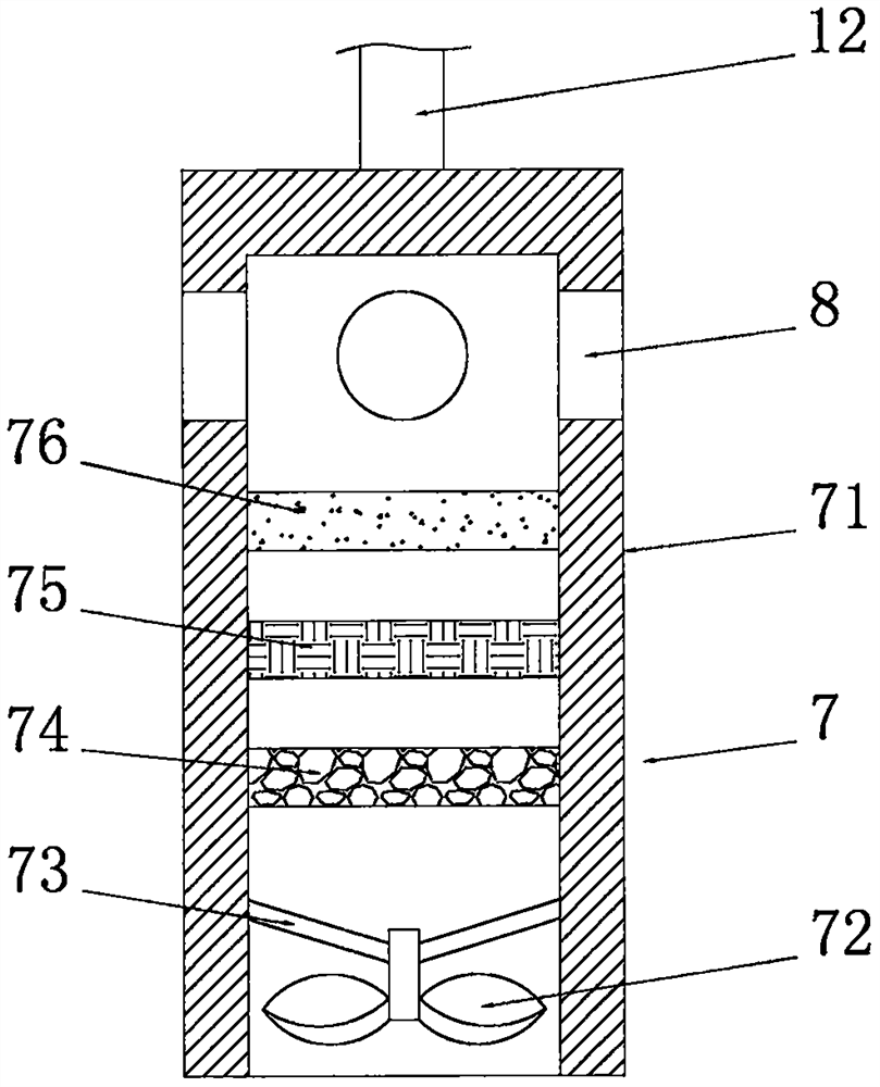
[0037] See figure 2 The difference from Embodiment 1 is that: the suction purification cylinder 7 includes a cylinder body 71, the cylinder body 71 is a cylindrical structure with an open bottom end, and the cylinder body 71 is sleeved in the air intake cylinder 3. The body 71 is threadedly connected to the air intake cylinder 3, the axis of the cylinder body 71 coincides with the axis of the air intake cylinder 3, and all the through holes 8 are arranged in a circular array on the outer surface of the cylinder body 71. The inner cavity of body 71 is provided with suction fan 72, water filtering layer 74, dust filter net 75 and activated carbon layer 76 successively from bottom to top, and described activated carbon layer 76 is located at the bottom of through hole 8, and described suction fan 72 passes through The fixed rod 73 is fixedly connected to the inner cavity wall of the cylinder body 71, and the outside air is drawn by the suction fan 72 into the air intake cylinder...

Embodiment 3

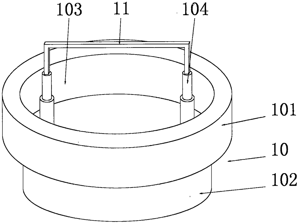
[0039] See image 3 The difference from Embodiment 1 is that the sealing cover 10 includes a cover plate 101 matching with the cleaning hole 9, and the bottom end of the cover plate 101 is fixedly connected with a sealing boss 102 matching with the cleaning hole 9, The sealing boss 102 is threadedly connected with the cleaning hole 9, and the spiral direction between the sealing boss 102 and the cleaning hole 9 is the same as the spiral direction between the cylinder body 71 and the air intake cylinder 3, and the top end of the cover plate 101 is provided with There is a storage chamber 103, and the bottom wall of the inner chamber of the storage chamber 103 is symmetrically provided with telescopic rods 104. The handrails 11 are fixedly installed on the tops of the two telescopic rods 104. By shrinking the telescopic rods 104, the handrails 11 can be The armrest 11 can be stored and stored in the storage cavity 103, which can effectively prevent the armrest 11 from being dama...


PUM


Abstract

The invention discloses a computer host structure for computer teaching, which comprises a case, wherein support legs are symmetrically arranged on the left and right sides of the bottom end of the case; air inlet cylinders are symmetrically arranged on the left and right sides of the bottom wall of an inner cavity of the case; the bottom ends of the air inlet cylinders are connected with the support legs through air inlet holes in a communicating manner; first protective nets are arranged in the air inlet holes; support plates are sleeved in the inner cavities of the air inlet cylinders; Thetop ends of the air inlet cylinders are in threaded connection with an air suction purification cylinders matched with the supporting plates; and a plurality of through holes are evenly formed in thetops of the outer circle faces of the air suction purification cylinders. External air is dragged by the air suction purification cylinders to enter the air inlet cylinders through the air inlet holes, then directly enters the air suction purification cylinders and finally flows into the case through the through holes, so that electrical elements in the case can be cooled. In the whole cooling process, air is subjected to dust removal and water removal purification treatment through the air suction purification cylinders, floating dust and water vapor in the air are removed, the floating dustcan be effectively prevented from covering the electrical elements, and therefore smooth operation of the electrical elements is guaranteed.

Description

technical field [0001] The invention relates to the technical field of computers, in particular to a computer host computer structure for computer teaching. Background technique [0002] The host computer refers to the main body part of the computer except the input and output devices. It is also a control box for placing the main board and other main components. Usually includes CPU, memory, motherboard, optical drive, power supply, and other input and output controllers and interfaces. Refers to the container used to place the motherboard and other major components in the computer hardware system. Usually includes CPU, memory, hard disk, optical drive, power supply, and other input and output controllers and interfaces, such as USB controllers, graphics cards, network cards, sound cards, and so on. Those located inside the main box are usually called internal devices, while those located outside the main box are usually called peripherals (such as monitors, keyboards, m...

Claims


Application Information

Patent Timeline
Patent Type & Authority Applications(China)
IPC IPC(8): G06F1/20G06F1/18B01D46/10B01D53/02B01D53/26
CPCB01D46/10B01D53/02B01D53/266B01D2253/102G06F1/183G06F1/20
Inventor 赵飒飒
Owner ZIBO VOCATIONAL INST
Learn More