Neodymium iron boron magnetic ring chamfering detection mechanism

A detection mechanism, neodymium iron boron technology, applied in the direction of measuring devices, instruments, etc., can solve the problems that the chamfering cannot be guaranteed to fit tightly, and the detection error is large, so as to achieve the effect of improving reliability and reducing error

Active Publication Date: 2020-12-11
长治市鑫磁科技有限公司
View PDF9 Cites 0 Cited by
  • Summary
  • Abstract
  • Description
  • Claims
  • Application Information

AI Technical Summary

Problems solved by technology

[0004] However, the above-mentioned chamfering detection equipment has the following problems: when the chamfering is detected, it cannot guarantee a close fit with the chamfering, resulting in a large detection error

Method used


Image

  • Neodymium iron boron magnetic ring chamfering detection mechanism
  • Neodymium iron boron magnetic ring chamfering detection mechanism
  • Neodymium iron boron magnetic ring chamfering detection mechanism

Examples


Embodiment Construction

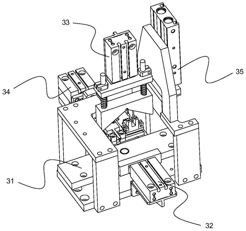
[0017] Such as figure 1 As shown in , a NdFeB magnetic ring chamfering detection device includes a conveying track 31 , a side pressing mechanism 32 , an upper pressing mechanism 33 , a chamfering detection mechanism 34 and a blocking mechanism 35 . The conveying track 31 is arranged obliquely, and the discharge end is at the bottom. The side of the feeding end of the conveying track 31 is respectively provided with a side pressing mechanism 32 and a chamfering detection mechanism 34. The upper part of the feeding end of the conveying track 31 is provided with an upper pressing mechanism 33. . The discharge end of the conveying track 31 is provided with a blocking mechanism 35 . The side pressing mechanism 32 is used to compress the side of the magnetic ring; the upper pressing mechanism 33 is used to compress the magnetic ring on the conveying track 31 from the top of the magnetic ring; the blocking mechanism 35 is used to compress the upper pressing mechanism 33 The magnet...


PUM


Abstract

The invention relates to the field of chamfering detection, in particular to a neodymium iron boron magnetic ring chamfering detection mechanism which comprises a conveying rail, a side face pressingmechanism, an upper pressing mechanism, a chamfering detection mechanism and a blocking mechanism. The conveying rail is obliquely arranged, the discharging end is arranged below the conveying rail, the side face of the feeding end of the conveying rail is provided with a side face pressing mechanism and the chamfering detection mechanism, and the upper portion of the feeding end of the conveyingrail is provided with the upper pressing mechanism. The blocking mechanism is arranged at the discharging end of the conveying rail. By arranging the upper second sliding rail, the lower second sliding rail and the first sliding plate, the second sliding plate and the first sliding plate can move respectively, meanwhile, under the action of the reset spring, it is guaranteed that the detection block on the second sliding plate can be tightly attached to the chamfer, the chamfer detection reliability is improved, and the detection error is reduced.

Description

technical field [0001] The invention relates to the field of chamfering detection, in particular to a chamfering detection mechanism of an NdFeB magnetic ring. Background technique [0002] In order to remove the burrs produced by machining on the parts and to facilitate the assembly of the parts, chamfers are generally made on the ends of the parts. The NdFeB magnetic coil in the present invention needs to be chamfered on the side to facilitate subsequent assembly. After chamfering, it is necessary to inspect the chamfering to determine whether the chamfering is in place. [0003] Existing chamfering detection equipment, such as the chamfering detection mechanism disclosed in the Chinese invention patent with the publication number CN104942657B, includes a base. The base has a workpiece detection cavity that can place workpieces, and is located on the base and located in the workpiece detection cavity. There is also a distance detector at the end of the workpiece. When th...

Claims


Application Information

Patent Timeline
IPC IPC(8): G01B21/22
CPCG01B21/22
Inventor 王加皮郭现伟胡景生
Owner 长治市鑫磁科技有限公司
Why Eureka
Try Eureka