Tile quality automatic detection equipment
An automatic detection and quality technology, applied in the direction of measuring devices, instruments, scientific instruments, etc., can solve the problems of inconsistent beating strength, effort, and easy to affect the accuracy of detection, so as to avoid the effect of too high height and reduce the distance
- Summary
- Abstract
- Description
- Claims
- Application Information
AI Technical Summary
Problems solved by technology
Method used
Image
Examples
Embodiment 1
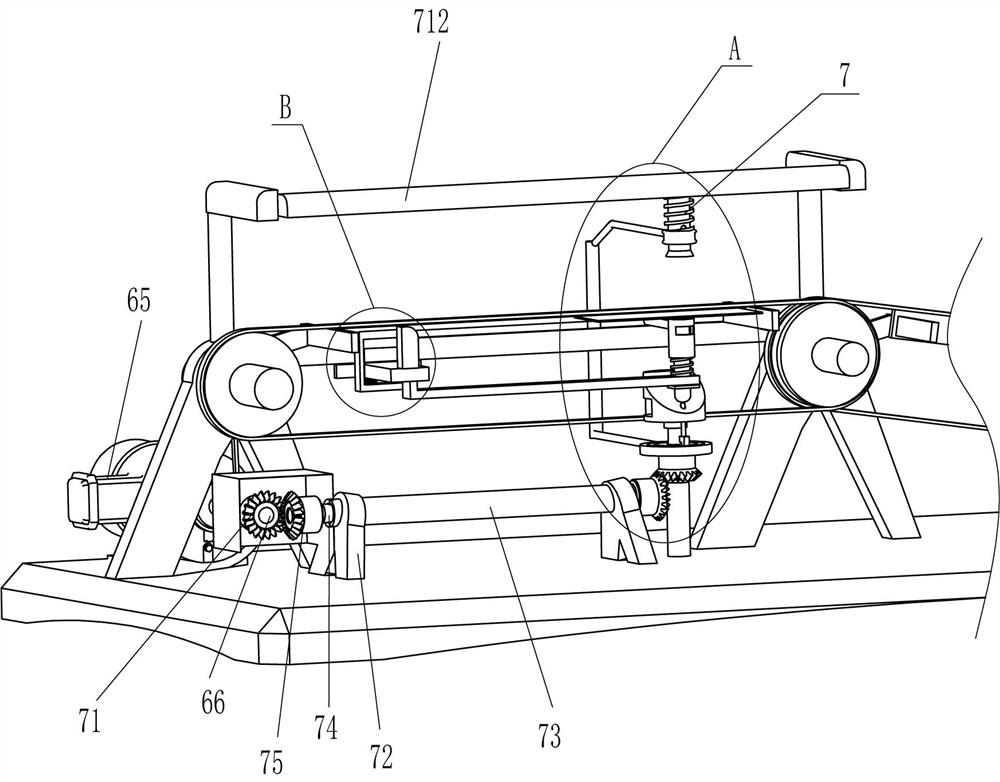
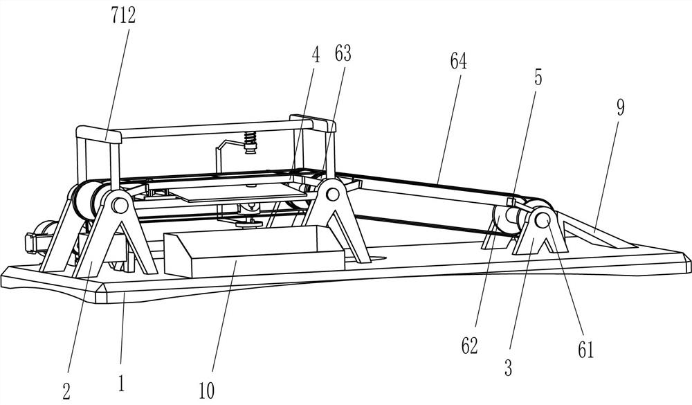
[0024] A tile quality automatic detection equipment, such as Figure 1-Figure 4 As shown, it includes a base 1, a riser 2, a first small support 3, a first support 4, a second support 5, a transmission mechanism 6, and a detection mechanism 7. There are vertical boards 2, a first small bracket 3 is fixed symmetrically front and back on the right side of the top of the base 1, a first support frame 4 is fixed between the top inner sides of the four vertical boards 2, and the upper right side of the right vertical board 2 is connected to the first A second support frame 5 is fixedly connected between the top of the left side of a small bracket 3, and a transmission mechanism 6 is arranged between the left rear part of the top of the base 1, four vertical plates 2 and two first small brackets 3, and the base 1 A detection mechanism 7 is arranged between the left side of the top, the right part of the first support frame 4 and the tops of the four vertical boards 2 .
[0025] The...
Embodiment 2
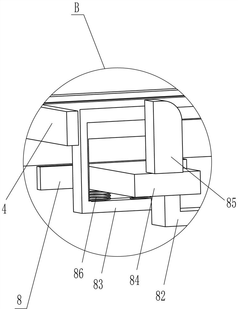
[0031] On the basis of Example 1, such as figure 2 , Figure 4 and Figure 5 As shown, it also includes a stopper mechanism 8. The stopper mechanism 8 includes a fixed block 81, a rectangular plate 82, a return block 83, a slide block 84, a block 85 and a second spring 86, and the front and back of the first support frame 4 The left side of the two sides is fixedly connected with a return block 83, and the slide block 84 is slidably connected between the front and rear sides of the return block 83. Two second springs 86 are connected between them, a stopper 85 is fixedly connected to the middle of the top of the slider 84, a rectangular plate 82 is fixed to the middle of the bottom of the slider 84, and the right part of the rectangular plate 82 is slidably set on the first sliding rod 710. In the lower circumferential direction, a fixed block 81 is fixedly connected to the lower circumferential direction of the first sliding rod 710 , and the top of the fixed block 81 is i...
Embodiment 3
[0034] On the basis of embodiment 1 and embodiment 2, such as figure 1 As shown, an L-shaped rubber block 9 is also included, and an L-shaped rubber block 9 is affixed in the middle of the top right side of the base 1, and the L-shaped rubber block 9 is located on the right side of the first transmission shaft 61 on the right side.
[0035] It also includes a waste collection frame 10 , the top front left part of the base 1 is fixedly connected with the waste collection frame 10 , and the waste collection frame 10 is located under the front side of the support plate 711 .
[0036] When the qualified tiles were driven by the right belt 64 to move to the right, the tiles were delivered to the L-shaped rubber block 9, and the tiles on the L-shaped rubber block 9 then slipped to the ground. Like this, can avoid that the height that tile falls from right belt 64 is too high and causes to break.
[0037] When the tiles fell to the left belt 64 and were broken, the broken tiles fell...
PUM
 Abstract
Description
Claims
Application Information
 - R&D
- Intellectual Property
- Life Sciences
- Materials
- Tech Scout
- Unparalleled Data Quality
- Higher Quality Content
- 60% Fewer Hallucinations
Browse by: Latest US Patents, China's latest patents, Technical Efficacy Thesaurus, Application Domain, Technology Topic, Popular Technical Reports.
© 2025 PatSnap. All rights reserved.Legal|Privacy policy|Modern Slavery Act Transparency Statement|Sitemap|About US| Contact US: help@patsnap.com


