Improved electric barring gear of marine main engine

A technology of ship main engine and electric crank, which is applied in the direction of machine/engine, mechanical equipment, engine components, etc., can solve the problems of manual installation of crank crank, multi-manual assistance, etc., to avoid jamming and ensure the effect of lubrication

Inactive Publication Date: 2020-12-08
倪文利
View PDF0 Cites 0 Cited by
  • Summary
  • Abstract
  • Description
  • Claims
  • Application Information

AI Technical Summary

Problems solved by technology

[0003] At present, most of the existing electric barring machines for main engines of ships on the market have the following deficiencies during use: the barring machines need to be manually installed and adjusted manually, which requires more manual assistance to complete, while the existing ships The electric barring machine for the main engine is not easy to solve such problems. Therefore, an improved electric barring machine for the main engine of the ship is urgently needed to solve the above problems

Method used


Image

  • Improved electric barring gear of marine main engine
  • Improved electric barring gear of marine main engine
  • Improved electric barring gear of marine main engine

Examples


Embodiment 1

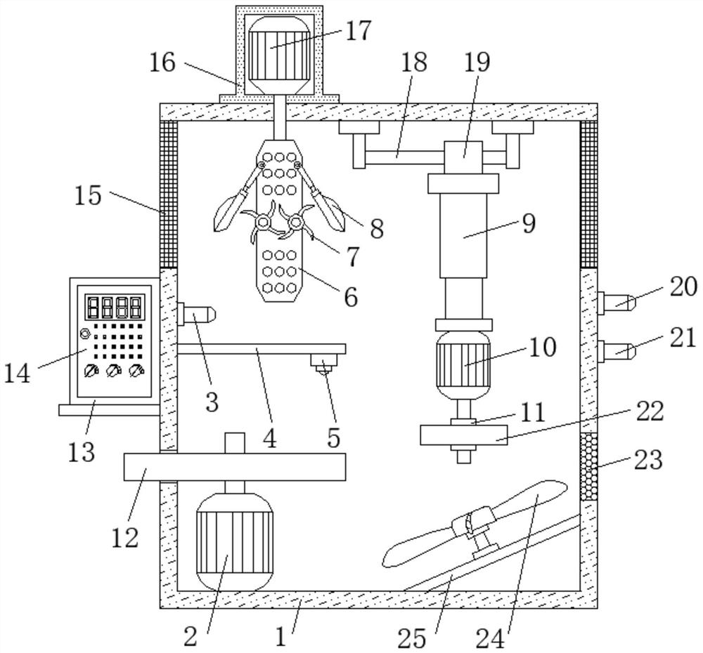
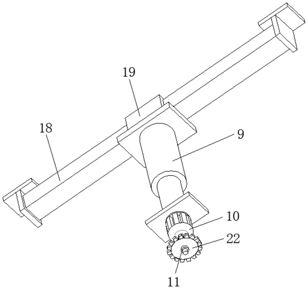
[0025] refer to Figure 1-2 , an improved ship main engine electric turning machine, including a box body 1 and a main motor 2, the main motor 2 is fixed on one side of the bottom inner wall of the box body 1 by bolts, and one end of the output shaft of the main motor 2 is sleeved with a driving wheel 12 One end of the driving wheel 12 is located outside the box body 1, and one side of the outer wall of the top of the box body 1 is fixed with an electric slide rail 18 by bolts, and a slider 19 is slidably connected to the outer wall of one side of the electric slide rail 18. An electric telescopic rod 9 is fixed on the outer wall of the bottom by a bolt, and one end of the extension rod of the electric telescopic rod 9 is fixed with a first motor 10 by a bolt. Both sides of the gear 22 are sleeved with the limit ring 11, and the position of the inner wall on one side of the box body 1 close to the driving wheel 12 is fixed with a horizontal plate 4 by bolts. The horizontal pla...

Embodiment 2

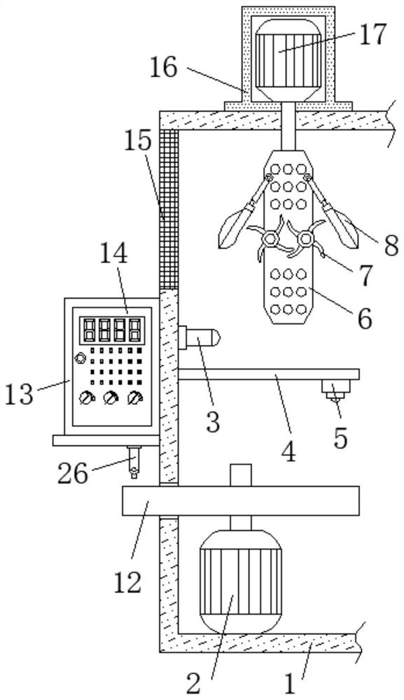
[0029] refer to image 3 , an improved ship main engine electric barring machine. Compared with Embodiment 1, this embodiment also includes a lubricant drop bottle 26, which is fixed by bolts on the outer wall of the bottom of the connecting plate near the position of the driving wheel 12.

[0030] During use, the lubricant dropping bottle 26 is located above the driving wheel 12, and the lubricant is dripped regularly, which can lubricate the gear position of the driving wheel 12, so that the driving wheel 12 can rotate more conveniently, and there will be no abnormal rotation, so that the jamming can be reduced. Dead situation occurs, guarantee that driving wheel 12 can work normally.


PUM


Abstract

The invention discloses an improved electric barring gear of a marine main engine. Aiming at the problem that a barring gear can only be completed through much human assistance, the scheme is proposedas follows. The improved electric barring gear comprises a box body and a main motor, wherein the main motor is fixed to one side of the inner wall of the bottom of the box body through bolts, one end of an output shaft of the main motor is sleeved with a driving wheel, one end of the driving wheel is located on the outer side of the box body, an electric sliding rail is fixed to one side of theouter wall of the top of the box body through bolts, a sliding block is slidably connected to the outer wall of one side of the electric sliding rail, an electric telescopic rod is fixed to the outerwall of the bottom of the sliding block through bolts, a first motor is fixed to one end of an extension rod of the electric telescopic rod through bolts, and one end of an output shaft of the first motor is sleeved with a driving gear. The rotating condition of the driving wheel can be observed conveniently to determine whether the driving wheel can work normally or not, so that the interior of the box body is cooled rapidly, lubrication of a driving wheel gear is guaranteed, and the jamming phenomenon in the rotating process is avoided.

Description

technical field [0001] The invention relates to the technical field of barring devices, in particular to an improved electric barring machine for main engine of a ship. Background technique [0002] Ship is a general term for various ships. A ship is a means of transportation that can sail or park in waters for transportation or operation. A ship is a man-made means of transportation that mainly operates in geographical waters. The main engine of a ship needs to be detected by a cranking machine before use. Whether the operation is normal, so it is necessary to use the electric barring machine for the main engine of the ship. [0003] At present, most of the existing electric barring machines for main engines of ships on the market have the following deficiencies during use: the barring machines need to be manually installed and adjusted manually, which requires more manual assistance to complete, while the existing ships The electric barring machine for the main engine is ...

Claims


Application Information

Patent Timeline
Patent Type & Authority Applications(China)
IPC IPC(8): F02B77/00F02B77/08F04D25/08F04D25/16F16H57/04G01K13/00
CPCF02B77/00F02B77/08F04D25/08F04D25/166F16H57/0465F16H57/0493G01K13/00
Inventor 倪文利孙健刘森
Owner 倪文利
Why Eureka
Try Eureka