


Quick Research
Generate reliable direction feasibility study reports for your R&D in just a few steps.

Technical Q&A
Discover and master advanced knowledge NOW. Basics, ideas, possibilities, all at once.

Find Solutions
As an expert in R&D theories, this can generate solutions to your technical problems instantly.

Evaluate Feasibility
Analyze your overall solution with one click, know your potential R&D risks in advance.

Monitor Landscape
Get weekly tech updates, stay abreast of the latest tech innovations and key insights.
A stacking device for automatic stacking cable tray production
A cable tray and stacking technology, which is applied in the field of stacking devices for automatic stacking cable tray production, can solve problems such as slow efficiency, inability to realize automatic stacking, and affecting production efficiency
- Summary
- Abstract
- Description
- Claims
- Application Information
AI Technical Summary
Problems solved by technology
Method used
Image

Examples
Embodiment 1
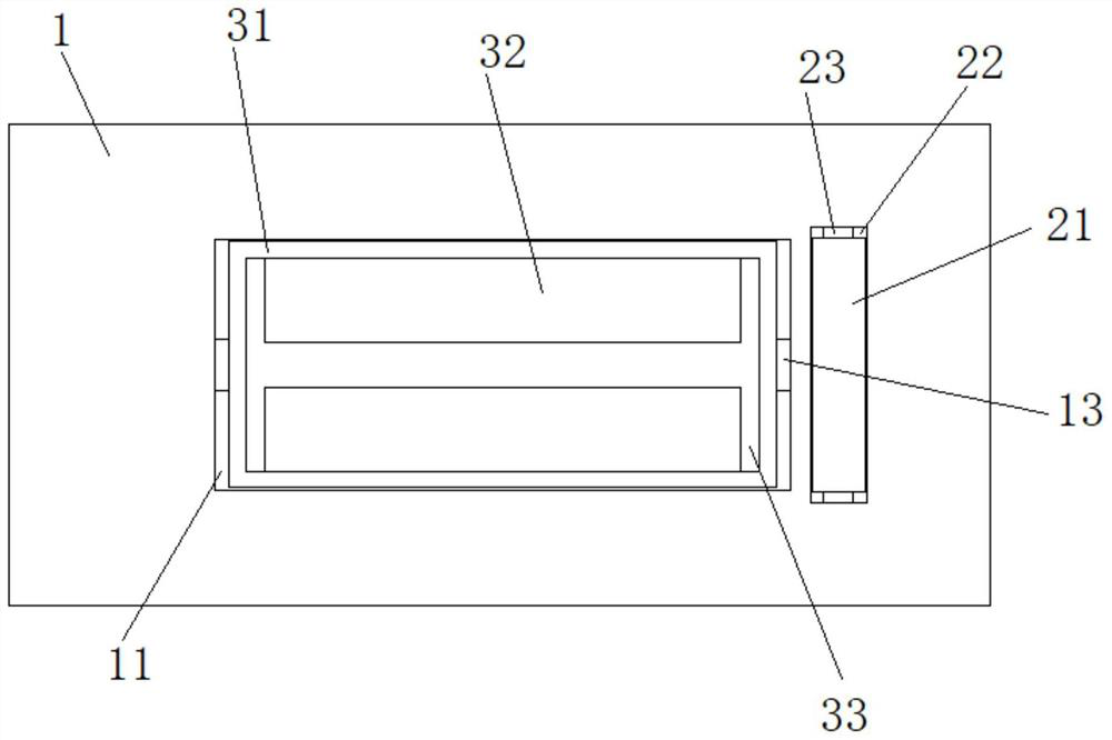
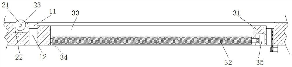
[0031] An automatic production of stacked type cable tray stacking apparatus comprising a stacking station, the stacking station 11 is provided on an alignment groove, the alignment grooves 11 of the through, the alignment groove 11 and the groove 12 features a rotating, the 12 equipped with a rotary drum rotating mass of said rotatable 31, the rotary block 31 equipped with the through locating slots 33, the positioning slot 33 side walls are equipped with symmetrical and rotatable plate 32 is reversed, the alignment grooves 31 of the rotating mass at the bottom 11 equipped with the movable plate 43 and down discharge.
[0032] Rotating mass, in conjunction with the flap, when laying the cable tray, it is possible inverted, thereby realizing a cable tray when stacked, vertically superimposed to automate to achieve the automatic laying cable trays, fast and efficient.
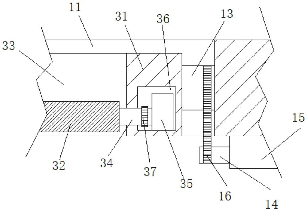
[0033] Preferably, both ends of the rotary block 31 is provided with a symmetrical distribution shaft 13, the rot...
Embodiment 2
[0038] Example 1 is not restated in common, different from Embodiment 1 in that:
[0039] See Figure 5-7 The discharge plate 43 is provided with a bottom support plate 41, the support plate is provided with two symmetrically distributed hydraulic rod 42 41, the hydraulic rod is rotatably connected to the form between the base portion 42 and the discharge end plate 43 the discharge plate 43 is equipped with a side discharge chute 431, the spout 431 may be equipped with a sliding connection and contraction motion of the plates 45 extend.
[0040] Further, the extension plate 45 at the bottom of the bottom plate 43 is provided with a discharge spout 431 communicates with the communicating groove 433, the extension bottom plate 45 features a uniform distribution of the rack 432, the communicating groove 433 equipped with gear 451 and rotatably engaged with the rack 432.
[0041] Still further, the bottom portion of the discharge plate 43 provided with an extension motor 453, the exten...
Embodiment 3
[0046] Example 1 is not restated in common, different from Embodiment 1 in that:
[0047] See Figure 1-4The codewater tank 22 is provided with a feed groove 22, and the feed groove 22 is provided with a rotatable feed roller 21, and the feed roller 21 is passed through a feed shaft. 23 is attached to the feed slot 22, and the feed motor is provided on one side of the feed slot 22 (not shown in the figure), and the feed motor output is connected to the feed shaft 21.
[0048] The design of the feed roller 21 makes the cable bridge in the code, the cable bridge can automatically enter the flip plate 32 in the code gauge 11, thereby realizing the automation of the code release, more efficient.
[0049] Example 3
[0050] See Figure 1-8 , An automatic stacked cable bridge production code arrangement, including a code release 1, and a code release 11 is provided, the code depositor 11 is penetrated, and the code release groove 11 is provided with a rotary slot 12, The rotary groove 12 ...
PUM
 Abstract
Description
Claims
Application Information
 - R&D Engineer
- R&D Manager
- IP Professional
- Industry Leading Data Capabilities
- Powerful AI technology
- Patent DNA Extraction
Browse by: Latest US Patents, China's latest patents, Technical Efficacy Thesaurus, Application Domain, Technology Topic, Popular Technical Reports.
© 2024 PatSnap. All rights reserved.Legal|Privacy policy|Modern Slavery Act Transparency Statement|Sitemap|About US| Contact US: help@patsnap.com