
On-machine inspection system and method for automatic tool focus adjustment based on machine vision

A detection system and machine vision technology, applied in the direction of manufacturing tools, measuring/indicating equipment, metal processing machinery parts, etc., can solve the problems of low detection efficiency, troublesome detection process, large space occupation, etc., to ensure rotation accuracy and stability , versatility and applicability improvement, and the effect of saving internal space

Active Publication Date: 2021-08-31
NINGBO SANHAN ALLOY MATERIAL CO LTD +1
View PDF7 Cites 0 Cited by
  • Summary
  • Abstract
  • Description
  • Claims
  • Application Information

AI Technical Summary

Problems solved by technology

[0004] (1) The current machine vision on-machine inspection system takes up a lot of space, and it is difficult to install it in the limited space of the machine tool in actual production. Therefore, most of the current tool inspection devices are separated from the machine tool. When performing inspection, the tool needs to be disassembled from the machine tool. For detection, the detection process is troublesome and the detection efficiency is low
[0005] (2) At present, a small number of tool detection systems can be installed in the limited space of the machine tool for on-machine detection, but it is often necessary to disassemble the workpiece or some machine tool components to install it, and the applicability and versatility of the device are not high
[0006] (3) The current tool on-machine inspection system does not have the focusing function or the automatic focusing function. When the specification of the tool to be tested changes, the image acquisition device cannot automatically adjust the focus to collect a clear image of the tool
[0007] (4) The current tool detection system can only detect a single surface of the tool at a time, and cannot obtain cross-scale images of the tool in the limited machine space, resulting in incomplete machine vision detection and low detection efficiency
[0012] This invention has high operability, short detection time, and high human-computer interaction, but it is necessary to take out various tools from the machine tool and place them on the corresponding X-axis three-jaw pneumatic fingers for clamping, which cannot realize on-machine detection of tools , it is also impossible to realize the on-machine detection during tool processing
[0013] To sum up, the development of relevant equipment in the existing technology is not perfect, and there are generally shortcomings such as inability to detect on-machine, unable to automatically adjust focus, low efficiency of single detection, and incomplete detection.

Method used


Image

  • On-machine inspection system and method for automatic tool focus adjustment based on machine vision
  • On-machine inspection system and method for automatic tool focus adjustment based on machine vision
  • On-machine inspection system and method for automatic tool focus adjustment based on machine vision

Examples


Embodiment 1

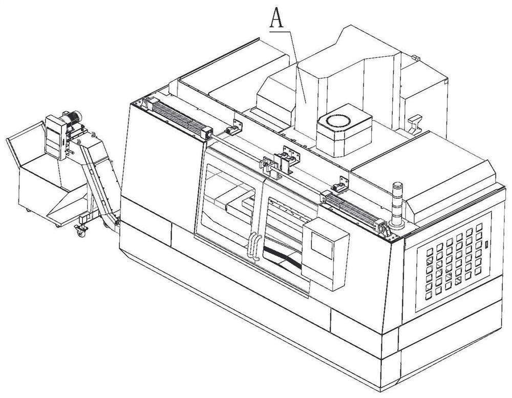
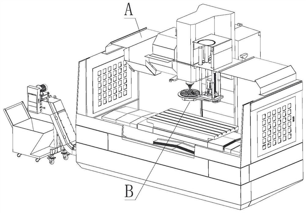
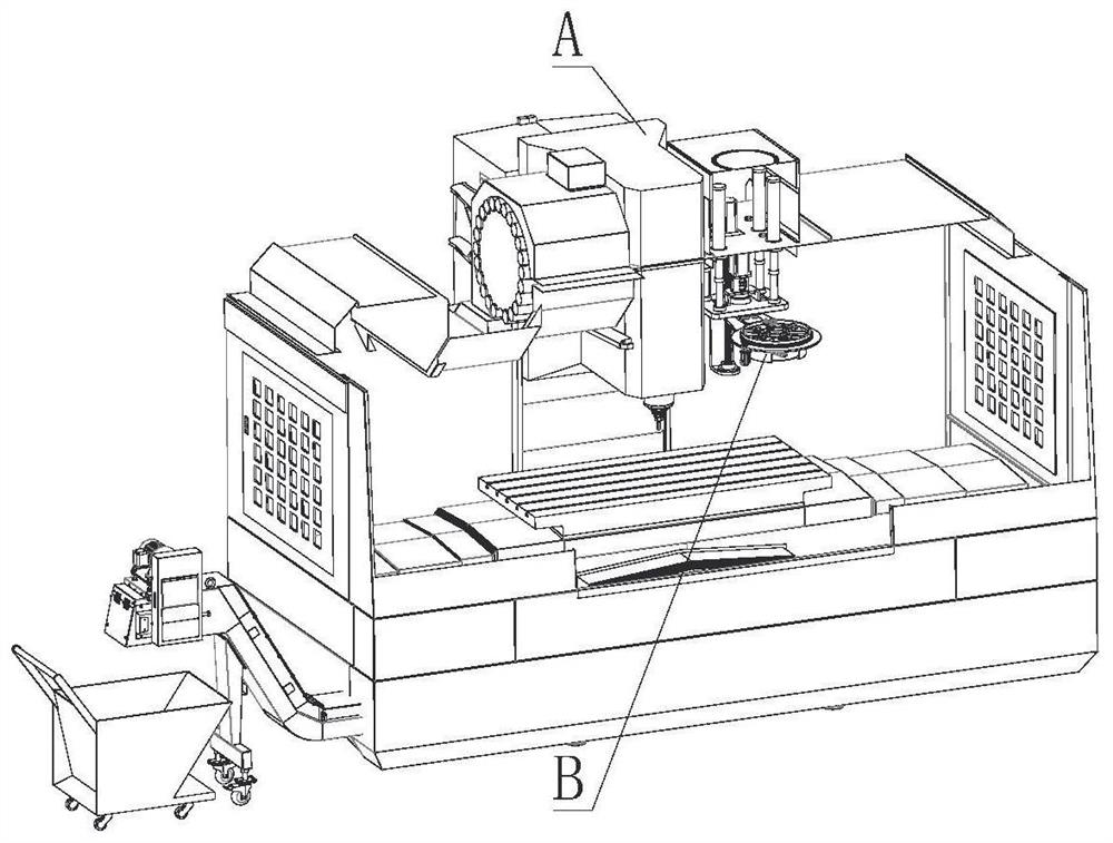
[0109] This embodiment provides an automatic tool based on machine vision focus detection system in the machine, with reference to attached figure 2 with figure 2 (A), the six detection system consists of extension drive device I, II webs, hexagon socket head cap screws III, IV hexagon socket head screws, hexagon socket head cap screws V and VI image pickup device composed of . Wherein the connecting plate is connected to one end of the I II by hexagon socket head cap screws III and IV hexagon socket head screws with the driving means. After installing the drive coupling plate II overall vertical distribution means I, I drive means can drive the rotation of the link plate II, II may be driven up and down movement of the connecting plate. Image pickup device VI is attached to the other end of the link plate II, which is set into the mounting hole from above the web II, II to Jiazhu web and to achieve both connection and positioning between the cylinder head by screws V.

[0110] Re...

Embodiment 2

[0126] This embodiment provides a method based on machine vision tools automatic focusing system of the working machine testing method, the current machining center tool most of the drill mill, with the cutter, for example, in the form of a special milling tool wear, In addition to flank wear, the cutter after Vice flank wear is also more serious, therefore the formulation of blunt criteria should take into account the tool flank wear deputy. Therefore, to deal with the image sensing edge and the end face of the drill mill is acquired during the image acquisition, and also to respond to the machine tool diameter is measured. One purpose of the installation to ensure that machine tool bed model is correct, to avoid staff negligence installed the wrong tool, the second is in accordance with the measured current actual diameter of the tool as a basis for the user to dynamically modify the parameters of the NC program. However, due to the machining center tool wide range of different ...


PUM


Abstract

The invention discloses an on-machine detection system and method for fully automatic focusing of cutting tools based on machine vision. The technical proposal includes: a drive device, a connection board, and an image acquisition device, and the image acquisition device and the drive device are connected through a connection board; the drive device includes The lifting mechanism and the rotating mechanism are detachably connected to the lifting mechanism and connected to the connecting plate; the image acquisition device includes a tool side edge and diameter image acquisition mechanism, a tool end face image acquisition mechanism and a focus adjustment mechanism, and a tool side edge and diameter image The acquisition mechanism is fixed above the focus adjustment mechanism, and the tool end face image acquisition mechanism is installed at the center of the focus adjustment mechanism. The invention collects tool images in the machining gap, and the detection process does not affect the production efficiency of the machining center, and can detect the tool wear in the process of processing in time; and can simultaneously collect images of the flank face and the attached flank face of each cutting edge of the tool and detection to improve detection efficiency.

Description

Technical field [0001] The present invention relates to the detection unit in the machining center tools, and more particularly, to a tool based on machine vision focus automatic machine detection system and method. Background technique [0002] Manufacturing industry is the pillar industry of the national economy today, its development is an important indicator of a country's comprehensive strength. China is a manufacturing country on the map, stage machinery manufacturing machining rely mainly on our annual big demand for the tool. Parameters and quality tools directly. Process quality and yield. With labor costs and increasing the degree of automation, machinery manufacturing industry currently use more unmanned, automated production, in order to ensure quality processing in an automated processing machine, the tool must be measured in the processing and use of tools in order to sure that the part quality, increase production efficiency, reduce production costs. In the metal c...

Claims


Application Information

Patent Timeline
Patent Type & Authority Patents(China)
IPC IPC(8): B23Q17/09B23Q17/24
CPCB23Q17/0914B23Q17/2452
Inventor 李长河李昊罡罗亮吉卫喜万斌辉尹硕曹华军卢秉恒唐立志崔歆刘明政张彦彬徐杰罗慧明徐海州杨敏洪华平高腾杨玉莹马五星陈帅
Owner NINGBO SANHAN ALLOY MATERIAL CO LTD
Learn More