


Quick Research
Generate reliable direction feasibility study reports for your R&D in just a few steps.

Technical Q&A
Discover and master advanced knowledge NOW. Basics, ideas, possibilities, all at once.

Find Solutions
As an expert in R&D theories, this can generate solutions to your technical problems instantly.

Evaluate Feasibility
Analyze your overall solution with one click, know your potential R&D risks in advance.

Monitor Landscape
Get weekly tech updates, stay abreast of the latest tech innovations and key insights.
Optical imaging system and imaging apparatus having same
An optical imaging system and image-side technology, applied in the field of lenses, can solve problems such as difficulties in lens implementation
- Summary
- Abstract
- Description
- Claims
- Application Information
AI Technical Summary
Problems solved by technology
Method used
Image

Examples
no. 1 example
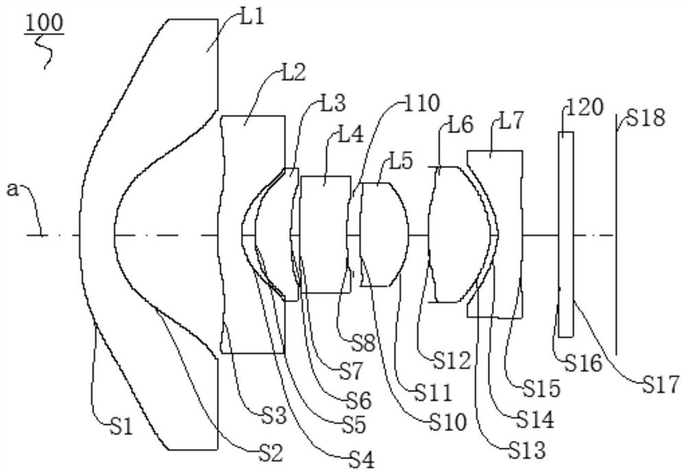
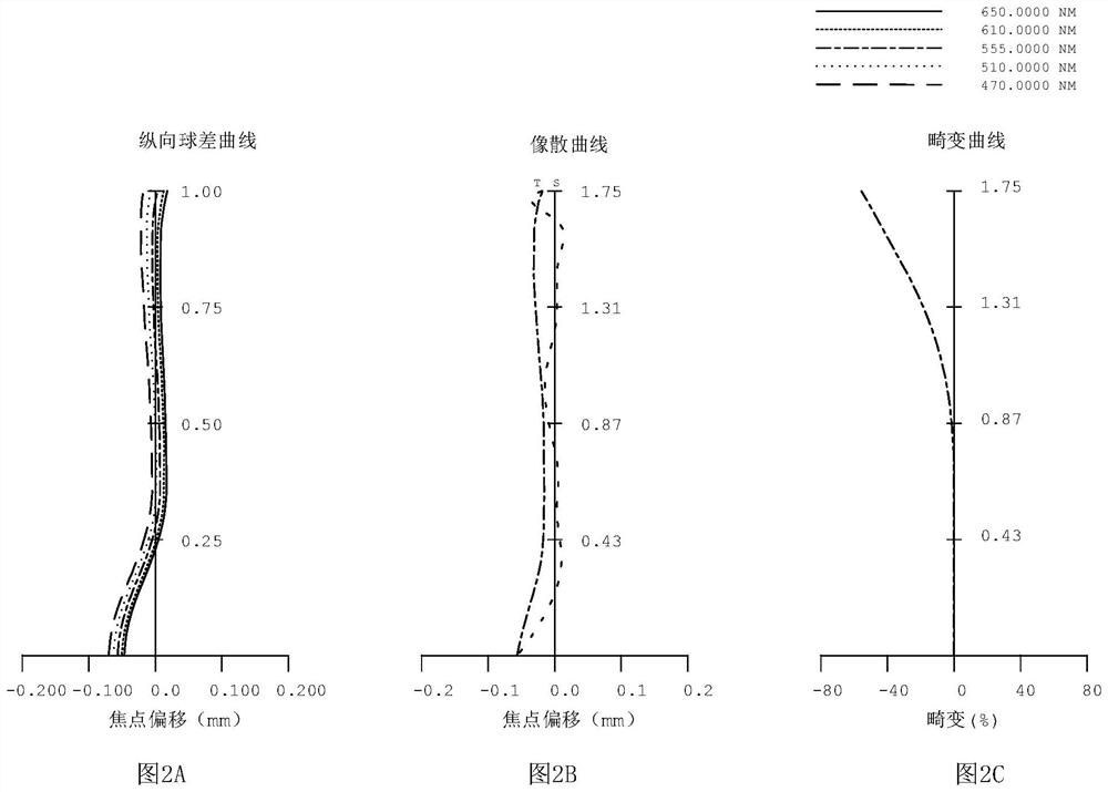
[0069] The optical imaging system of the first embodiment comprises from the object side to the image side of the distribution: a first lens L1, second lens L2, third lens L3, a fourth lens L4, a diaphragm 110, a lens L5 of the fifth, sixth lens L6, a seventh lens L7, an infrared cut filter 120 and an image plane S18. The optical system of the first embodiment of the focal length f = 0.941mm, aperture FNO = 1.9 °, the angle of view FOV = 153 °, the total length of the system TTL = 7.448mm.
[0070] The first lens L1 having a negative refractive power, and a plastic material. Object-side surface to the optical axis paraxial region S1 is convex and the image-side surface S2 is a concave surface paraxial region; object-side surface in the circumferential paraxial region S1 is convex and the image-side surface S2 is a concave surface paraxial region; and the object side surface S1, like the side S2 are aspherical.
[0071] The second lens L2 has a negative refractive power, and a plas...
no. 2 example
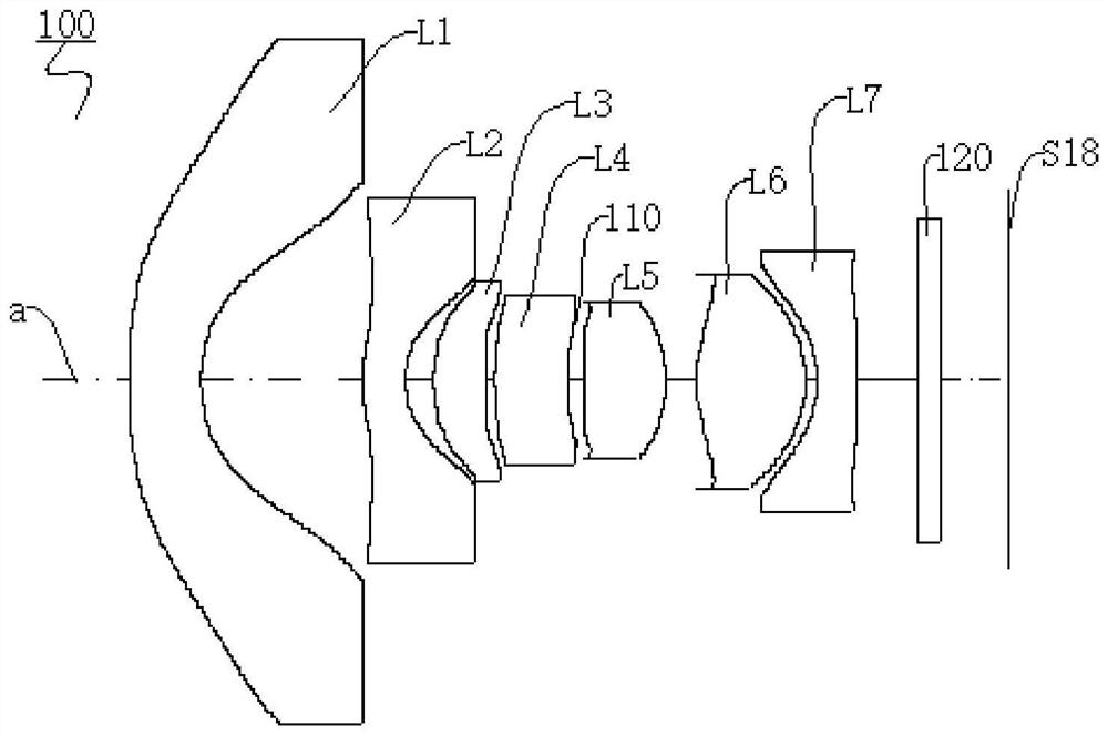
[0091] The optical imaging system of the second embodiment includes sequentially distributed from the object side to the image side: the first lens L1, the second lens L2, the third lens L3, the fourth lens L4, aperture 110, the fifth lens L5, the sixth The lens L6, the seventh lens L7, the infrared cut filter 120, and the imaging surface S18. The focal length f = 0.94128mm of the optical system, aperture FNO = 1.9 °, visiting angle FOV = 153.2 °, the total length of the system TTL = 7.459mm.
[0092] The first lens L1 has a negative dysfunction, and is a plastic material. The optical axis surface S1 is a convex surface having a convex surface having a concave surface in the near-axis region of the side surface S2; in the axial portion of the circumferential side surface S1, the outermost area of the side S2 is a concave surface; and the side surface S1, As the side surface S2 is aspherical.
[0093] The second lens L2 has a negative dysfunction, and is a plastic material. The s...
no. 3 example
[0111] The optical imaging system of the third embodiment includes sequentially distributed from the object side to the image side: the first lens L1, the second lens L2, the third lens L3, the fourth lens L4, aperture 110, the fifth lens L5, the sixth The lens L6, the seventh lens L7, the infrared cut filter 120, and the imaging surface S18. The focal length f = 0.939 mm of the optical system, the aperture FNO = 1.96 °, the angle of view FOV = 152.4 °, the total length of the system TTL = 7.368mm.
[0112] The first lens L1 has a negative dysfunction, and is a plastic material. The optical axis surface S1 is a convex surface having a convex surface having a concave surface in the near-axis region of the side surface S2; in the axial portion of the circumferential side surface S1, the outermost area of the side S2 is a concave surface; and the side surface S1, As the side surface S2 is aspherical.
[0113] The second lens L2 has a negative dysfunction, and is a plastic material....
PUM
 Abstract
Description
Claims
Application Information
 - R&D Engineer
- R&D Manager
- IP Professional
- Industry Leading Data Capabilities
- Powerful AI technology
- Patent DNA Extraction
Browse by: Latest US Patents, China's latest patents, Technical Efficacy Thesaurus, Application Domain, Technology Topic, Popular Technical Reports.
© 2024 PatSnap. All rights reserved.Legal|Privacy policy|Modern Slavery Act Transparency Statement|Sitemap|About US| Contact US: help@patsnap.com