
An optical system adjustment device capable of real-time compensation and its adjustment method

An optical system and real-time compensation technology, applied in the direction of using optical devices, optics, optical components, etc., can solve the problems of wasting time, the adjustment personnel cannot directly obtain the detection data of optical lenses, and the interval compensation data cannot be obtained, so as to increase the reliability Operability, improve the efficiency of assembly and adjustment, and the effect of loose lens tolerance

Active Publication Date: 2021-11-23
CHANNGCHUN CHANGGUANG ADVANCED OPTICS TECH CO LTD
View PDF14 Cites 0 Cited by
  • Summary
  • Abstract
  • Description
  • Claims
  • Application Information

AI Technical Summary

Problems solved by technology

The existing assembly and adjustment process prevents the assembly and adjustment personnel from directly obtaining various inspection data of optical lenses, let alone real-time interval compensation data. It is necessary to inspect the lenses that have been installed and adjusted, and the designer proposes a renovation plan based on the inspection results , disassemble the lens and reassemble it, a lot of time is wasted, and it needs the cooperation of inspection and design personnel to complete

Method used


Image

  • An optical system adjustment device capable of real-time compensation and its adjustment method

Examples


Embodiment Construction

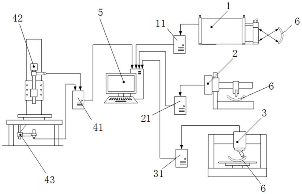
[0021] Such as figure 1 As shown, the real-time compensable optical system adjustment equipment of the present invention includes a laser interferometer 1, a depth measuring instrument 2, an interferometer 3, a centering instrument 42, a mirror locator 43, and a calculation unit 5; a laser interferometer host 11, Depth measuring instrument host 21 and interferometer host 31 are respectively connected to the input of the calculation unit, and the output of the centering instrument 42 and the mirror locator 43 is connected to the input of the calculation unit 5 through the adjustment host 41; the laser interferometer 1, the depth measuring instrument, the interferometer The measuring instrument transmits the measured surface shape accuracy, thickness, and surface curvature radius of each lens to the calculation unit 5 respectively.

[0022] For the first lens of the optical system, the calculation unit 5 calculates the adjustment guidance data according to its theoretical adjust...


PUM


Abstract

The invention relates to a real-time compensating optical system installation and adjustment equipment. The laser interferometer, depth measuring instrument and interferometer of the equipment respectively transmit the measured surface shape accuracy, thickness and surface curvature radius of each lens to the calculation unit, The centering instrument monitors and adjusts the lens inclination and eccentricity online and transmits the measured data of the lens inclination angle and eccentric distance to the calculation unit; the mirror positioner measures the distance between the lens and the previous lens and transmits the measured data to the calculation unit; for the first lens of the optical system , the calculation unit calculates the adjustment guidance data according to its theoretical adjustment data and independent variable parameters; for any subsequent lens, the calculation unit calculates the adjustment according to its theoretical adjustment data, independent variable parameters and the accumulated deviation value of the actual detection data of the previous lenses. Lens adjustment guide data. The invention can perform real-time compensation according to the actual detection data of each lens, guide the adjustment of the next lens, and realize the rapid adjustment of the high-end microscopic objective lens.

Description

technical field [0001] The invention belongs to the technical field of optical system adjustment, and relates to an optical system adjustment device capable of real-time compensation and an adjustment method thereof. Background technique [0002] With the rapid development of optoelectronic technology, a large number of high-end lenses have appeared in various fields such as scientific research and life, such as high-end microscope objectives. The optical performance of these lenses is not only related to the surface accuracy, smoothness, and roughness of the optical lens, but also closely related to the tilt eccentricity of the lens and the distance between the mirror surfaces. Therefore, high-precision optical adjustment technology becomes the key to determine the performance of the lens. To achieve high-precision optical adjustment, it is necessary to accurately measure the surface shape accuracy, radius of curvature, center thickness and other data of the optical lens, a...

Claims


Application Information

Patent Timeline
Patent Type & Authority Patents(China)
IPC IPC(8): G01B11/24G01B11/255G01B21/08G01M11/00G02B27/62
CPCG01B11/2441G01B11/255G01B21/08G01M11/00G02B27/62
Inventor 管海军王超徐放谢晓麟张继真曲贺盟
Owner CHANNGCHUN CHANGGUANG ADVANCED OPTICS TECH CO LTD
Learn More